-
Welcome to Overclockers Forums! Join us to reply in threads, receive reduced ads, and to customize your site experience!
You are using an out of date browser. It may not display this or other websites correctly.
You should upgrade or use an alternative browser.
You should upgrade or use an alternative browser.
The Sled Acrylic Tech Bench
- Thread starter Jolly-Swagman
- Start date
- Joined
- Sep 20, 2007
- Thread Starter
- #22
Oh Lordy this is gonna be a beaut! Can't wait for the unveiling of the finished product!
Thank,s ihrstrdr
Going to look great with that M/B getting from you!
You said it ih... man, that's looking mighty nice there JS!
Quite an organized guy too I see...
Thanks harlam357,
Yeah lol, everything has its place,
- Joined
- Sep 20, 2007
- Thread Starter
- #23
# Update 10-24-2009
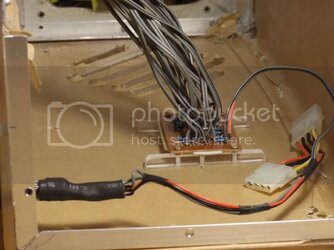
In this Update I have wired the Power Reset Switches, LED,s for PWR - HDD activity and Mounted them, also Mounted the PCB LED power Resistor board on its own little Sled Plexi Rails, and wired LED Power Switch to control the Case LED Lighting,
Also did some more work on the HDD Cage , Cut out my insignia JS into the Plexi,
and Mounted in The Sled
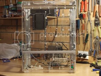
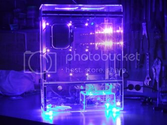
Now there is also a Special Part of this Update and I think everyone has been anxiously waiting for, the Unveiling of the Plexi,
Well Stay Tuned as it is coming right up , see below!!!
PCB Board for Resistors Powering LEDs, and LED Power Switch

HDD Cage with Insignia Cut-out


Now lets get The Sled Naked and Unveil the Plexi
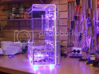
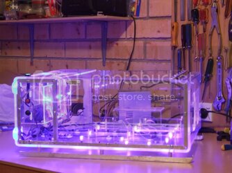
The Sled Unveiled Pics


That's all for NOW!!!
Have some more Pics on the way too of the DVD Drive - Card Reader bay Cages
Also some Lighting Up the Sled Pics too Unveiled, very soon going to have Diner first, so keep ya in suspense till then,,,,jajajaja
Also did some more work on the HDD Cage , Cut out my insignia JS into the Plexi,
and Mounted in The Sled
Now there is also a Special Part of this Update and I think everyone has been anxiously waiting for, the Unveiling of the Plexi,
Well Stay Tuned as it is coming right up , see below!!!
PCB Board for Resistors Powering LEDs, and LED Power Switch
HDD Cage with Insignia Cut-out
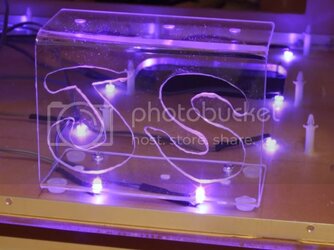
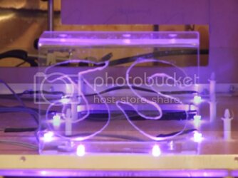
Now lets get The Sled Naked and Unveil the Plexi
The Sled Unveiled Pics
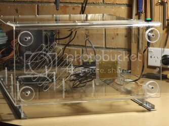
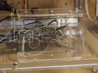
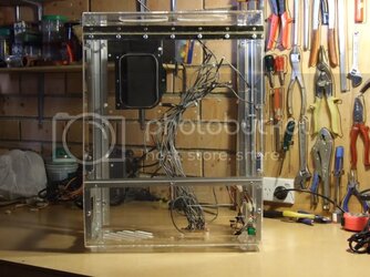
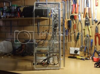
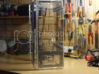
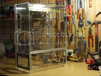
That's all for NOW!!!
Have some more Pics on the way too of the DVD Drive - Card Reader bay Cages
Also some Lighting Up the Sled Pics too Unveiled, very soon going to have Diner first, so keep ya in suspense till then,,,,jajajaja
- Joined
- Sep 20, 2007
- Thread Starter
- #25
Lookin' good, can't wait to see it all finished up and full of parts!
Thanks pejsaboy, just waiting on Parts coming from USA (Motherboard) & Canada (PSU), before I can put the Hardware in.
The PSU from Canada that Oklahoma Wolf is sending will go in my Main Rig and then swap my PSU to Wifes Rig and her PSU to use in The Sled
This ECS p45t-a skt775 Motherboard from ihrsetrdr, will be used in The Sled
- Joined
- Sep 20, 2007
- Thread Starter
- #26
# Update 10-25-2009
- Joined
- Sep 20, 2007
- Thread Starter
- #27
# Update 10-27-2009
This Update will incorporate Making Top Fan Grill for the 2 Top Exhaust Fans, Mounting the Fans, and Testing them ,
Making the Top Fan Grill,
Decided to make a Acrylic Plexi Fan Grill for the Top fans
Cutting Out the Plexi for the Fan Grill

Clean Up & Filing the Cutouts for Fan Grill

As well as Filing I also used this Dremel tool In the Ozito Rotary Tool

The Top Fan Grill

Had to run down to the Hardware Shop to get some Screws to Mount the Fans, using 5/32" x 25mm Metal Threads
Antec Fans, Screws and Fan Grill

120mm Fans Installed in the Top

Fan Grill Installed

Installed 120mm Side Fan and Fan Grill,
Although I think I will make another for the Side Intake, similar to the Top one!
Tested all OK and Now Lighting Up with Fans Too!

Angled View Lighting with Fans Installed

Well that about it for this Update,,
Stay Tuned for more soon!!
Making the Top Fan Grill,
Decided to make a Acrylic Plexi Fan Grill for the Top fans
Cutting Out the Plexi for the Fan Grill
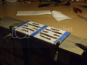
Clean Up & Filing the Cutouts for Fan Grill
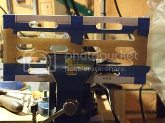
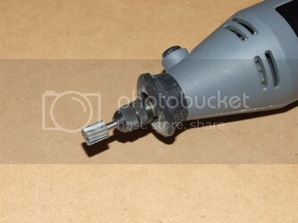
As well as Filing I also used this Dremel tool In the Ozito Rotary Tool
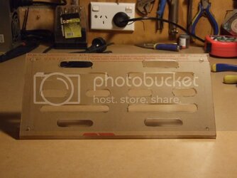
The Top Fan Grill
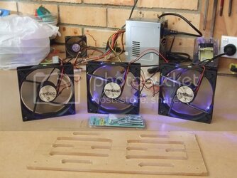
Had to run down to the Hardware Shop to get some Screws to Mount the Fans, using 5/32" x 25mm Metal Threads
Antec Fans, Screws and Fan Grill
120mm Fans Installed in the Top
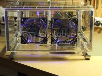
Fan Grill Installed
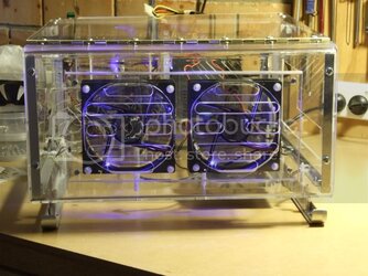
Installed 120mm Side Fan and Fan Grill,
Although I think I will make another for the Side Intake, similar to the Top one!
Tested all OK and Now Lighting Up with Fans Too!
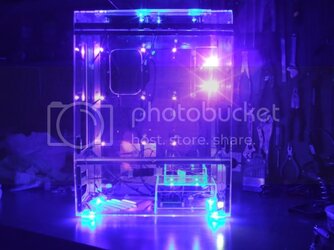
Angled View Lighting with Fans Installed
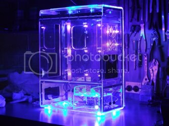
Well that about it for this Update,,
Stay Tuned for more soon!!
- Joined
- Jun 13, 2006
- Location
- Park Hills, Missouri
awsome case im ready to see this thing is some action
- Joined
- Sep 20, 2007
- Thread Starter
- #29
awsome case im ready to see this thing is some action
Thanks sephiroth_749,
Just waiting on Hardware Parts coming from USA (Motherboard) & Canada (PSU), before I can put the Hardware in.
The PSU from Canada that Oklahoma Wolf is sending will go in my Main Rig and then swap my PSU to Wifes Rig and her PSU to use in The Sled
This ECS p45t-a skt775 Motherboard from ihrsetrdr, will be used in The Sled
-------------------------------------------------------------------------
# Update 10-28-2009
Just a small Update today, made another Acrylic Fan Grill to match the Top Fan Grill, this one will go on the 120mm Side Intake Fan.
Cutting-out new 120mm Acrylic Fan Grill

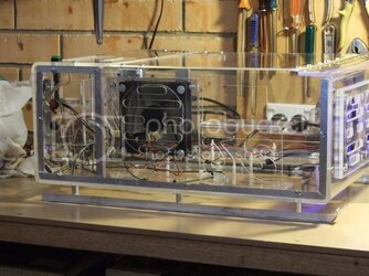
Mounted Acrylic 120mm Side Fan Grill

Close-up Of Side Acrylic Fan Grill

Also put some Strong Black Fibreglass Fly wire behind Grill as this is an Intake Fan will help keep the Dust Bunnies Out,,,
Well that's all folks for Todays Update!!
Stay tuned for more to come soon!!
Cutting-out new 120mm Acrylic Fan Grill
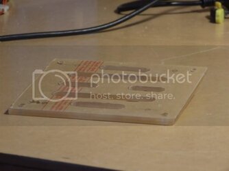
Mounted Acrylic 120mm Side Fan Grill
Close-up Of Side Acrylic Fan Grill
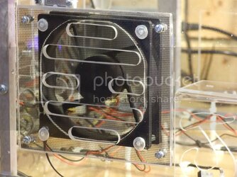
Also put some Strong Black Fibreglass Fly wire behind Grill as this is an Intake Fan will help keep the Dust Bunnies Out,,,
Well that's all folks for Todays Update!!
Stay tuned for more to come soon!!
- Joined
- Sep 20, 2007
- Thread Starter
- #30
#Update 10-30-2009
Not allot going on Today was hot here, and had bit of Headache, also Wife not well at the moment either, and the Heat hasnt been helping,
So just a Small Update,
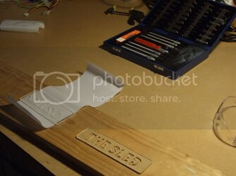
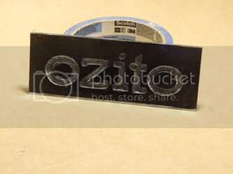
Have been working on the Ozito Emblem, Put some Clear Film (like what you cover books with) to Test out how it looks Painted at back,
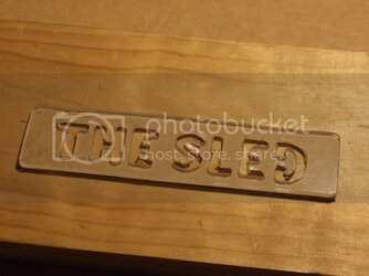
Also Made a The Sled Name badge too, from 3mm Acrylic
Working on Ozito and Sled Badges

The Sled Name Badge

The Ozito name Badge ( Testing Black Painted back)

Not a big Update ,, so thats all for Now!
Stay Tuned for more soon!!
So just a Small Update,
Have been working on the Ozito Emblem, Put some Clear Film (like what you cover books with) to Test out how it looks Painted at back,
Also Made a The Sled Name badge too, from 3mm Acrylic
Working on Ozito and Sled Badges
The Sled Name Badge
The Ozito name Badge ( Testing Black Painted back)
Not a big Update ,, so thats all for Now!
Stay Tuned for more soon!!
- Joined
- Sep 20, 2007
- Thread Starter
- #31
# Update 11-02-2009
Just a small Update, New Video The Sled Acrylic Tech Bench Vol 2
Video Log - The Sled Acrylic Tech Bench Vol 2
Thats, all for now, hope you Enjoy!
Video Log - The Sled Acrylic Tech Bench Vol 2
Thats, all for now, hope you Enjoy!
- Joined
- Sep 20, 2007
- Thread Starter
- #32
# Update 11-5-2009
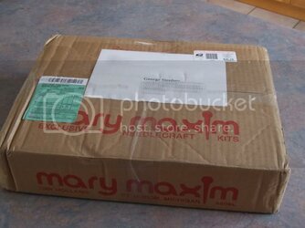
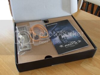
Today I Received a nice Parcel from a good Friend (ihrsetrdr) here @ OCForums, I recently Purchased an ECS-P45T-A - Black Series Motherboard from him and its now here.
The Parcel

The contents of the Parcel - The ECS-P45T-A Motherboard

Contents of M/B Box

The P45T-A Black Series Motherboard
This Motherboard is Dual PCi-E-16x v2.0 and X-fire Capable
Although I wont be doing X-Fire on it, Dont own or use ATI GPU,s but there will be 2x Nvida GPU,s going in for Folding@home GPUv2 (Most likely 2 x 8800GT,s)

This Motherboard is so Nice it May even end up in My Main Rig and one of My other M/B,s may go into The Sled,
Still undecided on at the Moment, and also still waiting on My 750Watt PSU coming from Canada too!
That,s all for Now!
Stay Tuned!
Today I Received a nice Parcel from a good Friend (ihrsetrdr) here @ OCForums, I recently Purchased an ECS-P45T-A - Black Series Motherboard from him and its now here.
The Parcel
The contents of the Parcel - The ECS-P45T-A Motherboard
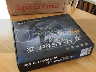
Contents of M/B Box
The P45T-A Black Series Motherboard
This Motherboard is Dual PCi-E-16x v2.0 and X-fire Capable
Although I wont be doing X-Fire on it, Dont own or use ATI GPU,s but there will be 2x Nvida GPU,s going in for Folding@home GPUv2 (Most likely 2 x 8800GT,s)
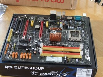
This Motherboard is so Nice it May even end up in My Main Rig and one of My other M/B,s may go into The Sled,
Still undecided on at the Moment, and also still waiting on My 750Watt PSU coming from Canada too!
That,s all for Now!
Stay Tuned!
- Joined
- May 17, 2005
- Location
- High Desert, Calif.
I'm glad it got there finally. 

- Joined
- Sep 20, 2007
- Thread Starter
- #34
I'm glad it got there finally.
Thanks ihrsetrdr, yes all nice a safely packed too for the long journey Downunder!!
Today is rather Hot in Mid 30C,s so A/C is running, bit hot and stuffy in Garage though, so when cools down a bit latter, will get around to testing out Mobo.
Will also have to Mod the PSU I have for testing to put in The Sled as cables to short especially the 4x ATX M/B power plug, need to extend them.
Stay Tuned for Updates Soon!!
- Joined
- Jun 16, 2001
Wow I must say very nice modding. Hope all goes well on that can't wait for more.
- Joined
- Jun 21, 2008
very nice so far! of course i would have preferred green leds  cant wait to see it loaded up with some hardware!
- Joined
- Sep 20, 2007
- Thread Starter
- #37
# Update 11-10-2009
Thanks Guy,s for your comments,
Still waiting for PSU to arrive from Canada, so will be finally installing all the hardware then!
Just another Small Update Today will Include a few things,
*Mounting and Testing ECS-P45T-A motherboard,on Motherboard Tray.
*Make a Backplate for the Acrtic Cooler Freezer Extreme Heatsink
*Install Windows 7 for testing Purposes,
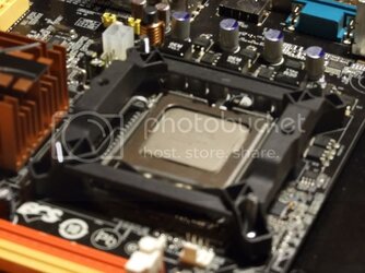
So first up I wasn't quite happy with the way the Arctic Cooling Freezer Extreme Mounted,
It has a Mounting plate and No Back plate just these tiny Pins that Lock the Mount Bracket in place on M/B
We all know how we hate those Push Pins on the Intel HSF and how in-effective they can be at times,
As with another of my HSF the Vendetta I did a Bolt Thru Mod on that, as well as the AC Freezer 7 pro
So here is My Solution to The AC Freezer Extreme Mounting,
First the intel Tiny Mount Pins

So I have made a Plexi Backplate for the Mounting Bracket
Making Plexi Backplate


Mounting Plate Installed on Backplate Bolt Thru

installing AC Freezer Extreme

Side Angle View

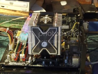
This HSF is a nice Beast too, and Now very secure, with my Backplate Bolt Thru Mod.
A little More of my Garage Workshop and Test Desk, Under the Desk is my Garage PC,
Testing the ECS Mobo in this Pic ( click for larger image)

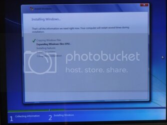
Installing Windows 7 for Test Purposes

CPU-z showing E2200 used for Testing (click for larger image)
http://i144.photobucket.com/albums/...uff/The Sled Tech Bench/The-SledCPUZe2200.jpg
and Memory for Testing Purpose (click for larger image)
http://i144.photobucket.com/albums/...Stuff/The Sled Tech Bench/The-SledCPUZMem.jpg
Core Temp

Overall even though is only Idle Temps at the moment was quite impressed as Todays Ambient was 35.5C and in the Garage was 30C when I was doing the Work Today,
Still wont be able to put all the Hardware into The Sled Acrylic Tech bech as My New PSU hasnt arrive and had to mod the one used for testing as the 4 x PSU ATX power lead is too short and so is the 24 Pin ATX to reach the Mobo when Installed
So hopefully wont be to much longer getting here from Canada
That,s all for Now!
Stay Tuned!
-------------------------------------------------------------------
*Mounting and Testing ECS-P45T-A motherboard,on Motherboard Tray.
*Make a Backplate for the Acrtic Cooler Freezer Extreme Heatsink
*Install Windows 7 for testing Purposes,
So first up I wasn't quite happy with the way the Arctic Cooling Freezer Extreme Mounted,
It has a Mounting plate and No Back plate just these tiny Pins that Lock the Mount Bracket in place on M/B
We all know how we hate those Push Pins on the Intel HSF and how in-effective they can be at times,
As with another of my HSF the Vendetta I did a Bolt Thru Mod on that, as well as the AC Freezer 7 pro
So here is My Solution to The AC Freezer Extreme Mounting,
First the intel Tiny Mount Pins
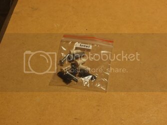
So I have made a Plexi Backplate for the Mounting Bracket
Making Plexi Backplate
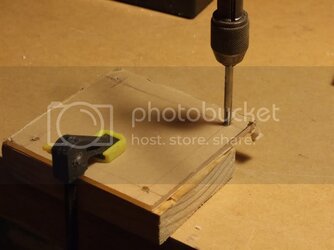
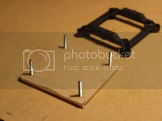
Mounting Plate Installed on Backplate Bolt Thru
installing AC Freezer Extreme
Side Angle View
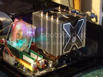
This HSF is a nice Beast too, and Now very secure, with my Backplate Bolt Thru Mod.
A little More of my Garage Workshop and Test Desk, Under the Desk is my Garage PC,
Testing the ECS Mobo in this Pic ( click for larger image)
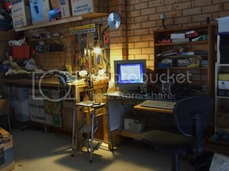
Installing Windows 7 for Test Purposes
CPU-z showing E2200 used for Testing (click for larger image)
http://i144.photobucket.com/albums/...uff/The Sled Tech Bench/The-SledCPUZe2200.jpg
and Memory for Testing Purpose (click for larger image)
http://i144.photobucket.com/albums/...Stuff/The Sled Tech Bench/The-SledCPUZMem.jpg
Core Temp
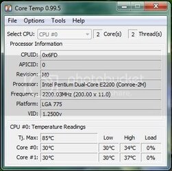
Overall even though is only Idle Temps at the moment was quite impressed as Todays Ambient was 35.5C and in the Garage was 30C when I was doing the Work Today,
Still wont be able to put all the Hardware into The Sled Acrylic Tech bech as My New PSU hasnt arrive and had to mod the one used for testing as the 4 x PSU ATX power lead is too short and so is the 24 Pin ATX to reach the Mobo when Installed
So hopefully wont be to much longer getting here from Canada
That,s all for Now!
Stay Tuned!
-------------------------------------------------------------------
Wow I must say very nice modding. Hope all goes well on that can't wait for more.
very nice so far! of course i would have preferred green ledscant wait to see it loaded up with some hardware!
Thanks Guy,s for your comments,
Still waiting for PSU to arrive from Canada, so will be finally installing all the hardware then!
Last edited:
- Joined
- Oct 15, 2009
- Location
- Canberra, Australia
Hey mate, been following the build, looks amazing!
- Joined
- Sep 20, 2007
- Thread Starter
- #39
Hey mate, been following the build, looks amazing!
Thanks sweetfu
- Joined
- Sep 20, 2007
- Thread Starter
- #40
# Update 11-14-2009
Today I have Put together a Tutorial on How I did the LED Circuit and PCB Board as a Request from TROJAN,and others too!
First off you need a PCB Vero Board which you can get from Most Electronic Parts outlets
EG- Radio Shack or an equivalent outlet!

The one I have Chosen ( Centred on Pic above) has alternating straight line RAIL,S and separate 2block segment Rows Between Rails
Some 560 Ohm Resistors, LEDS, and some Wire ( I have used some Speaker Cable)
Soldering Iron and Solder ( I use 1.0mm 60%tin/40%lead Hobby Solder)
Also Helps a Great Deal too If you have a PCB Holder too acts as an extra pair of hands.
Below is a Basic LED Layout Diagram of the Circuit I have Used for 17 LED.S
(Click Pics for larger image)

The only Difference to the Diagram Above is I have the + Positive Rail going to my Resistors, and Negitive Rail going to LEDS -negtive Leg
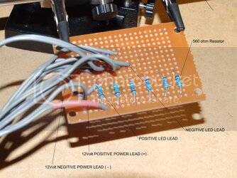
As you can see here I have started to put some of the Resistors on the PCB

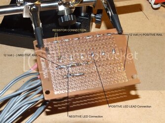
And the reverse side showing the PCB Rails

As you can see the Resistors go between the +12 volt Rail and one of the 2block Segment Rails, the the LED leads +positive go to the other end of Resistor and the -negative lead to the Negative Rail
Now if you have this all done correctly we have Power to LED.S

Hope this will be Helpful to TROJAN, a NewModCity Citizen and any other Members here that needed to know how to power LED.S using a PCB Power Grid Array..
Stay Tuned for More Updates soon!

TROJAN an NewModCity citizen wanted to know how did you made the LED circuit . Also a few Members from Here too, requested info
Today I have Put together a Tutorial on How I did the LED Circuit and PCB Board as a Request from TROJAN,and others too!
First off you need a PCB Vero Board which you can get from Most Electronic Parts outlets
EG- Radio Shack or an equivalent outlet!
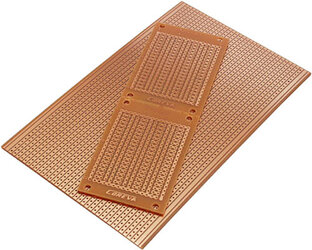
The one I have Chosen ( Centred on Pic above) has alternating straight line RAIL,S and separate 2block segment Rows Between Rails
Some 560 Ohm Resistors, LEDS, and some Wire ( I have used some Speaker Cable)
Soldering Iron and Solder ( I use 1.0mm 60%tin/40%lead Hobby Solder)
Also Helps a Great Deal too If you have a PCB Holder too acts as an extra pair of hands.
Below is a Basic LED Layout Diagram of the Circuit I have Used for 17 LED.S
(Click Pics for larger image)
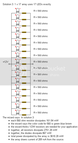
The only Difference to the Diagram Above is I have the + Positive Rail going to my Resistors, and Negitive Rail going to LEDS -negtive Leg
As you can see here I have started to put some of the Resistors on the PCB
And the reverse side showing the PCB Rails
As you can see the Resistors go between the +12 volt Rail and one of the 2block Segment Rails, the the LED leads +positive go to the other end of Resistor and the -negative lead to the Negative Rail
Now if you have this all done correctly we have Power to LED.S

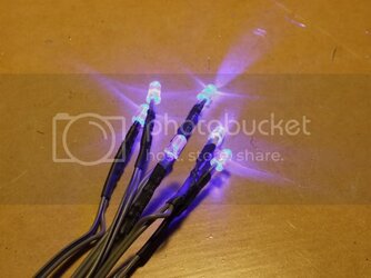
Hope this will be Helpful to TROJAN, a NewModCity Citizen and any other Members here that needed to know how to power LED.S using a PCB Power Grid Array..
Stay Tuned for More Updates soon!

Similar threads
- Replies
- 11
- Views
- 1K
- Replies
- 138
- Views
- 19K
