• Welcome to Overclockers Forums! Join us to reply in threads, receive reduced ads, and to customize your site experience!

FEATURED Building PWM Controller for 4 wires PWM fan

Overclockers is supported by our readers. When you click a link to make a purchase, we may earn a commission. Learn More.
Hope you get better Bob!

Looks good to me.
I love PCB's and dabbling with circuits and stuff, but I won't lie. I have no idea where to begin even building a circuit like that.
So hat's off to you :D
 
Start with Eagle and a schematic, go from there :D
Make yourself a PCB for a 555 fan controller or something, that'd be fairly simple but still complex enough to be satisfying.

That's what I did, never taken a class in this stuff.
 
Start with Eagle and a schematic, go from there :D
Make yourself a PCB for a 555 fan controller or something, that'd be fairly simple but still complex enough to be satisfying.

That's what I did, never taken a class in this stuff.

I second what he said.

Also, there are some excellent articles in the internet covering mixed signal circuit board design principals. I learned mountains about designing a circuit board by studying those articles and diagrams.

Specifically this one: http://www.cn-william.com/uploadfil...te/Design Considerations for Mixed-Signal.pdf

Also, it helps to think of the circuit board as just another electrical component. This is better visualized by considering that ground planes of sufficient size can act as capacitors. A good case in point of the aforementioned concept are the pcb pads used for touch capacitance applications. The touch of a human finger alters the capacitance of the metal pad on the pcb. If it didn't have a capacitance, you couldn't measure the change caused by the added capacitance of the human finger. Also, a small inductor can be created with circular expanding traces on a circuit board. All the circuit board really encompasses is a more efficient method of interconnecting other parts. It's a rats nest of wires laid flat and attached to large ground and power planes. Once you start to consider that, it becomes easier to visualize signal interference between components, heat from traces, electromagnetic field issues, etc...

An inductor on a pcb, so cool:
pcb-coils-03.jpg
 
Last edited:
I made a quick SMD 555 PWM PCB last night, it wasn't too complicated. Through hole would probably be even easier. I try to squeeze things as much as possible, which takes time.

I can provide the schematic for you if you want, then you can play with the board layout thing.

It has an auto-route traces button, if you're concerned about that. It's not especially good at its job, but it does work.
I route them all manually now, mostly for practice.

EDIT:
Actually I'll post the schematic for a through hole version here for everybody. I don't think I can make it open HW as it's not mine (it's Nidec's), but I can publish it at least.

2.EDIT:
Attached is a no libraries needed schematic with all through hole parts. Molex will have to be off-board as the stock Eagle libraries do not have a molex header. Fan header will fit the pin header holes just fine, do NOT wire it backwards. It will not be appreciated by the fan.


3.EDIT:
Unrelated to this posts's previous contents, the buck regulator now has a knob attached to vary voltage output, it's sustaining my ~4a Delta 3p fan at 8.5v 2.5a quite happily. I'm letting it sit to cook and see how hot it gets / if it explodes / etc. So far things look promising.

4.EDIT:
It's still running, temps have plateaued at ~52°c. All devices on the board are rated for 150°c, so that's fine. Perfectly happy running my 3pin delta. Steady state it draws 3.3a at full speed. If I do a quick snap from 2v to 12v the draw peaks at ~5 amps, which the controller can deal with.
 
Last edited:
Eagle does have a molex. It just doesn't have a silkscreen correct.

Use the KK-156 molex connector in eagle. It solders right up to the wires from a molex header; check the pictures on my blog where I described my device.
 
Ahh cool, that's good to know, thanks.

Now to make this into a fan control board and see how much it'll cost.

EDIT:
I'm giving Serious Consideration to using screw terminals (link to example) for almost everything and letting the buyer figure out wtf they want, or buying a crimp tool and pins to make various input adapters.
 
Last edited:
Ahh cool, that's good to know, thanks.

Now to make this into a fan control board and see how much it'll cost.

EDIT:
I'm giving Serious Consideration to using screw terminals (link to example) for almost everything and letting the buyer figure out wtf they want, or buying a crimp tool and pins to make various input adapters.

I recommend these:

http://www.monoprice.com/Product?c_id=102&cp_id=10245&cs_id=1024501&p_id=1316&seq=1&format=2

You can cut off the end you're not going to use and solder the wires. Very easy and worth the extra cost to provide a nice 10 inches or so of cable.

I used one here:

img_0286.jpg
 
So who wants to help me with my stupidity. So I wanted 2 PWM cpu fans to use on my D5400XS. i got 4 EFC1212DE's to mount to some Megahalems. Problem is, well, they aren't the 4 Wire fans i was hoping for. It's instead of a 4th PWM wire, it's a voltage sense wire. So based on the voltage going into it, the fan speed is adjusted. Purpose is to remove the 12V mains from the drive circuitry. So like PWM, but without it. So it's possible for me to still use pwm, but i just need a 12V pwm signal, correct?


EDIT: problem, they look for a 24V sense signal, not 12 :(

EDIT2: Would it be better if i just got different fans, and cry cause i don't know what to do with these?
Fans below
View attachment 142974

EDIT3: Forget it, they obviously can't be PWM controller. Opened one of them up, look at this
View attachment 142986
that Red wire looks like it's just attached to the yellow wire. just by a capacitor or resistor.... Is this just a Double tach fan?
 
Last edited:
Do you have a datasheet I can look at? Based on the part number it ought to be a 12v fan.

Edit: looks like an external pull up for the tach wire.
 
No datasheets for you Bob, So would this just be the equivelent of a 3 wire? other thing, it's a 1.2 amp like my EFB1212SHE so it should reach 2K rpm, but 12V into brown gets me 2100RPM. I hate this fan already. Wanna send all of them back for 2 TFC1212DE's with real pwm :'(
 
Got all the bits for the rev1.1 fan controllers. Have not assembled them. They should work.

Got all the bits for the motherboard PWM booster, assembled them, they work great.

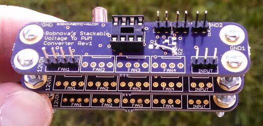
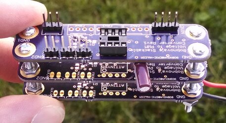
Got all the bits for the stackable voltage to PWM converters, assembled them, they make annoying noise due to the regulator not liking the bulk output cap. Removed bulk output cap, regulator is very happy with just a 0.1µF cap next to the MCU. Works great.
Forgot to order the small MOSFET and resistors for it, oops. Hence the flying bridge.
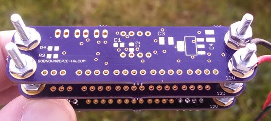
Pictures of the stackable thing follow. Ignore the electrolytic cap hanging out the side, that was an experiment and is not part of the design.
The bolts are 4-40.

stack1.jpg
stack2.jpg
stack3.jpg
 
That's nice and neat looking bob! :thup:

Hehe can't wait to see the finished product.
So how many can be stacked? As many as needed?
 
That's nice and neat looking bob! :thup:

Hehe can't wait to see the finished product.
So how many can be stacked? As many as needed?

Eventually the 12V bolt will melt, but other than that the sky is the limit. Bolt is probably good for at least 20 amps I'd say.
Other than 12V and GND all the boards are their own entities. You can have some run inverted PWM, some run normal, some run low frequency, some run high, etc.
Each board has an input plug for the voltage signal to come in, and four output plugs to power fans and send the PWM signal out.
One PCB per channel, essentially. Each PCB should be able to power and PWM at least 5 amps worth of fans or ~200 fans, which ever comes first.
They're set up for angled fan connectors to be used.
12V and GND are provided to the boards via one bolt for 12V and up to 3 for ground. Crimp on or solder on eye connectors to wires to a Molex is the recommended method. Wires can be soldered directly as well, if needed.
 
Wow, look really nice. Is this the controller you are working on is for me? because I see 10 fans connection on the board. I assumed this is the one is being built to power 10 of my 4.8a delta fans. I got your PM said is was tested and workining nicely. I must said this is it.?
 
Nope the the above is for Sandrat, it's the voltage to PWM converter.
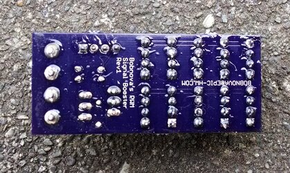
Your booster / splitter boards are being posted to the classies even as I type this.
Thread will be up in the cooling section of said classies shortly. (EDIT: It's been posted in the Cooling section of the classies now now)

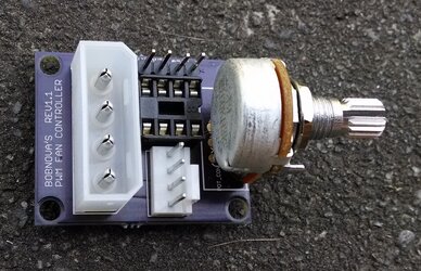
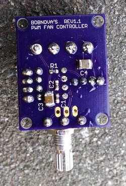
Here, however, are pictures!

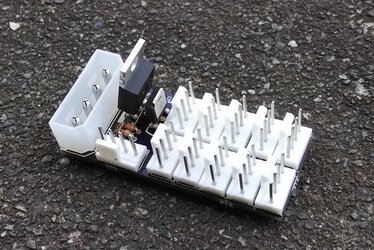
Active PWM Booster / Splitter:

rev1-top.jpg
rev1-bottom.jpg


Rev1.1 of the Attiny85 fan controller:

rev1-1-top.jpg
rev1-1-bottom.jpg
 
Last edited:
Back