• Welcome to Overclockers Forums! Join us to reply in threads, receive reduced ads, and to customize your site experience!

Get Your Cold Plate Thickness Calculation Here

Overclockers is supported by our readers. When you click a link to make a purchase, we may earn a commission. Learn More.

LabRat23

Member
Joined
Jun 27, 2004
Location
VA
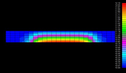
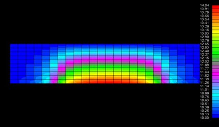
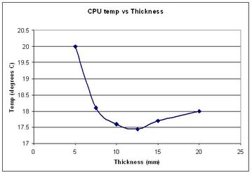
Just because I can, I came up with a formula to sort of calculate the optimum thickness of a cold plate. As we know, the heat flow towards the
edges of the coldplate increases per unit temperaure with thickness while
the heat flow straight up decreases.

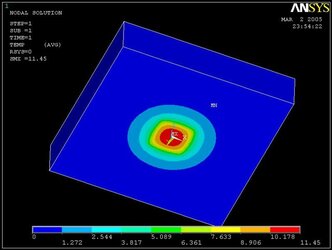
For simplicity, I am modeling the heat flux as a perfectly radial system.
Symbols used:
r1 = the radius of the cpu
r2 = the radius of the coldplate
r3 = reletive radius (r/r2) wich has a maximum value of 1 and a minimum
of 0
th = the thickness of the coldplate.

The sum of the thermal resistance can be simplified to the sum of the
thermal resistance in the radial direction and the thermal resistance in
the vertical direction.

The equation for thermal resistance of a section of thick walled pipe is
ln(r2/r1)/(2pi*th*k). This only acounts for constant heat flux. This
equation must be modefied to allow for heat loss off the faces. The
vetical heat loss as a function of radius is exponential due the fact
that the surface is two dimentional. The remaining heat is therefore
1-r3 squared. Since the heat flux is equal to a constant times the
temperature gradiant, the temperature gradiant is also (1-r^2) times the
tempurature gradiant of a the thick walled section of pipe. Integrating
from 0 to 1 to find the relative thermal resistance leaves us with a
value of exactly 1/4. Therefore the equation for a radial plate losing
heat off its face is ln(r2/r1)/(8pi*th*k).

We are not done yet. The heat flux towards the outside does not follow a
linear path. The path initially is a vertical up from the cpu, bends
horizontal, then bend vertical again. The actaul distance is therfore
not r2 but r2 + th*pi/2. This leaves us with
ln((r2+th*pi/2)/r1)/(8pi*th*k).

The eqation of the verticle heat transfer directly from the cpu straight
up to the tec is much simpler. It is th/(k*r1^2).

To find the total resistance of we combine the two equations, but it is
not as simple as adding them together. We need to take into acount the
relative amounts of heat traveling in the radial and verticle direction.
This amount is proportional to the the surface area of the TEC and the
surface area of the CPU die. The relative radial heat flux is
(r2^2-r1^20)/r2^2. The reletive vertical heat flux is r1^2/r2^2
Our fisrt equation would then be (r2^2-r1^20)/r2^2 *
ln((r2+th*pi/2)/r1)/(8pi*th*k). Our second equation is r1^2/r2^2 *
th/(k*r1^2), which simplifies to th/(r2^2*k).

Our final equation is (r2^2-r1^20)/r2^2 * ln((r2+th*pi/2)/r1)/(8pi*th*k)
+ th/(r2^2*k).

For those of you who do not want to compute this by hand the number of
times it would take to find the optimum value of th, fear not. I have
made this Excel function.

=LN((C1+1.57*A1)/B1)/(8*3.14159*A1*10)*(C1^2-B1^2)/C1^2+A1/C1^2/10

Just copy and paste it into Excel, put your guess for the optimum
thickness into cell a1, CPU die radius into b1, and your tec radius into
c1. If you know how, there is a solver tool that will find the value of
cell a1 that produces the smallest value of your function. Units are in
inches.

An added bennefit is that you can now find the thermal resistance of your
coldplate.

For a quick example, a coldplate (r2 = .98) on my 3.2e (r1 = .2) the
optimum thickness is .245inches and I get a thermal resistance of
.055C/W.

A final word of caution, we are simplifiying the system into a radial
system, which in reallity is square. I guestimate the error to be at the
very worst to be 5%. Also, this does not acount for the IHS. If you have
one, I would suggest you add maybe half the thickness of the IHS into the thickness of the coldplate to compensate.

Hope this helps you all.
 
Very nice work. (Assuming your equation is right. I'm not going to check. ;) )

It's interesting to note that the difference in thermal resistance, between a 5mm coldplate and a 10mm coldplate, is a factor of 10 less than the thermal resistance of a good quality TIM joint to the CPU. (See here post 60 for a table of plausible thermal resistance values for a variety of thermal goops.)

Would it be reasonable for you to compute heatflux into the TEC as a function of radius?

I suspect that a coldplate on the thicker side (10mm) would be better, because of the more even distribution of the heatload over the surface of the TEC.
 
Would it be reasonable for you to compute heatflux into the TEC as a function of radius?

Probably not. First, I do not believe that sort of thing can be calculated by hand. Secondly, I have my doubts that there is much variance in the heat flux. The heat flux is not dependent on the temperature difference. Conversly, the heat flux is the constant that we compute our temperature difference with. The temperature variance will simply be propogated to the top of the TEC and that is where the difference in performance will be found, at the waterblock. I believe that any perpormance increases of the waterblock would be offset by the greater resistance on the coldplate.
 
I'm interested in how accurate this calculation is. I don't quite understand what the thick wall pipe equation is for (assuming smaller radius is 0?). I'm not one to do all that math mayself though, so I'm thinking I should see if ANSYS gets simillar results to what you have. The best way I can think to model this problem would be like they have in the square block on this page: link

edit: forget the link, I think you have to be on UBC's server to get to it.

The idea is to apply a thermal flux over the area the processor touches and hold the other side of the cold plate at a constant temperature. You can then find the total thermal impeadance from:

Resistance = (Tsource-Tbase) / Power

A slightly more realistic aproach might be to apply convection against the cold plate, as this would more accuratly model the effect of the pelt. Using a bulk temperature of whatever the temperature of the pelt would be with no load, and then using a fairly high convection coefficient would probably model it pretty accuratly. This way areas of the pelt with more load would not be as cold, and the outer edges would be colder. Unfortunatly this more accurate model would depend highly on the value of the convection coefficient and there is no way to really figure that out..... :-/

I'll try the simpler model later and see what I get.
 
Last edited:
Here is a thermal model of a cold plate / heat spreader. This is a cross section of a 4mm and a 10mm thick copper plate , both are 48mm x 48mm. In the center at the bottom, I put a 70 Watt heat source. On the top I held it at 10C with a TEC or any other device you would like, but it is the same size as cold plate (48mm x 48mm). As you can see by the temp scale on the right of both the models, thicker is not better. The 10mm thick plate a runs about 2C hotter than 4mm thick plate.
 

Attachments

  • 4mm coldplate 70 W heat  .jpg
    4mm coldplate 70 W heat .jpg
    20.4 KB · Views: 3,121
  • 10mm coldplate 70 W heat .jpg
    10mm coldplate 70 W heat .jpg
    28.7 KB · Views: 3,063
doc said:
Here is a thermal model of a cold plate / heat spreader. This is a cross section of a 4mm and a 10mm thick copper plate , both are 48mm x 48mm. In the center at the bottom, I put a 70 Watt heat source. On the top I held it at 10C with a TEC or any other device you would like, but it is the same size as cold plate (48mm x 48mm). As you can see by the temp scale on the right of both the models, thicker is not better. The 10mm thick plate a runs about 2C hotter than 4mm thick plate.

Hi doc,

Thanks for providing those model results.

One thing I wonder about, is whether treating the cold side of the TEC as an isothermal plane is a very accurate representation of the behavior of a TEC in this situation. As you well know, (but other readers may not) the TEC's we buy are actually an array of small TEC modules. I would assume as you move out from the center of the TEC, the heat pumped through each module goes down and the dT across the module goes up.

Thoughts?
 
matttheniceguy said:
This way areas of the pelt with more load would not be as cold, and the outer edges would be colder. Unfortunatly this more accurate model would depend highly on the value of the convection coefficient and there is no way to really figure that out..... :-/

I noticed your post after I had replied to doc, and see that you are bringing up somewhat the same point.

Using a convection coefficient might be the most practical method of modelling this with readily available (to some) tools. However, the behavior of TEC's is reasonably well defined and it might not be impractical to include realistic TEC behavior in a model.

I don't have access to any such tools myself, but would be very interested in the results of such modelling.

BTW your link isn't working for me.
 
OK, forget about modeling the cold plate as a heat flux and an isothermal plane. It seems like it might make a decent model, but it really won't. You will just keep getting cpu temperatures closer and closer to the temperature of the isothermal plane as you reduce the thickness of the plate. The isothermal plane doesn't account for the ability of different areas of the pelt to only be able to handle a certian amount of heat transfer with a certian delta T.

Here is a pic of a coldplate from ANSYS. The top was held at 0 celcius and the cpu was modeled as a 1cm square putting out 100 watts. Obviouslt if you were to make the plate thickness 0 the cpu temp would be 0, which is deffinatly not what would happen with a pelt, so the model doesn't work.

As an alternative to a heat flux for the cpu and convection on the cold plate, I am wondering of you could model it as a heat flux for the pelt, a heat source for the cpu, and some other sort of convection on the cpu or pelt to determine temperatures from....
 

Attachments

  • 10mm.JPG
    10mm.JPG
    41.6 KB · Views: 4,770
Hi Since87 and Mattheniceguy,

First I’d like to reply to Since87. An isothermal plane is not the best way to accurately do this. However to prove a point, that thicker is not always better, it was ok. I agree that a TEC has many small devices inside and each one provides some dT and dQ and has a gradient around the contact surface area. A good TEC will have very small distances between devices which makes the gradients small. So as an approximation , what I did was ok because I was more interested in what happens as a function of cold plate thickness and not the absolute temps.

Second I’d like to reply to Mattheniceguy. I was not making a case for no cold plate, because some thickness is needed. However when it gets to thick, it starts working against you not for you. No cold plate is a special case because the TEC’s substrate become the cold plate, it is very thin but also not very thermally conductive compared to metals , so now the thermal gradients move into the TEC’s substrate and we would look at the cold surfaces of the TEC. Again as I stated above it is not meant to be accurate as far as what temp someone would have using these two cold plates, but more as a principle. There is a optimum thickness for a specific metal and heat spreading only improves to a point, after that it has diminishing returns and then it has negative returns . How thick is too thick, depends on the metal and conditions. But in most cases 4 to 6 mm will work good much thicker than that will get into negative returns.

It is good that you guys question this and have some ideas as to whats going on, also it keeps me on my toes and makes me think is this correct or am I blowing smoke up someones butt.
 
doc said:
First I’d like to reply to Since87. An isothermal plane is not the best way to accurately do this. However to prove a point, that thicker is not always better, it was ok. I agree that a TEC has many small devices inside and each one provides some dT and dQ and has a gradient around the contact surface area. A good TEC will have very small distances between devices which makes the gradients small. So as an approximation , what I did was ok because I was more interested in what happens as a function of cold plate thickness and not the absolute temps.

I posted a link to this thread at ProCooling here, because I knew some there might be interested in the subject.

BillA brings up some very good points, and Les provides links to some of his calculations regarding coldplate thickness.

Having thought on it some more, my intuition (mental model, whatever) says that any model of the temperature distribution inside the coldplate, that doesn't model the TEC behavior realistically, is likely to be way off. The outer areas of the TEC are going to drop in temperature until they "suck" enough heat away from the center to keep them from reaching dTmax@v.

Wish I had some tools to play with this stuff, but it would be too painful to try to do in Excel or Pspice. I'd say BillA's comments should be closely heeded.
 
BillA said:
an excellent non-CFD program for TEC assys is TAS by Harvard Thermal

Took a look at the website. TEC support seems to be limited to modelling TEC's that Melcor produces which seem to top out at a Qmax of 135 Watts or so. Possibly useful for modelling systems of interest, if all relevant scaling is done correctly.

They have a demo version available but it is limited to 300 nodes and doesn't allow saving models. I found a price of 17K for one of their specialized software offerings. Don't think I'll be ordering it soon.
 
yup, our TEC supplier cannot provide all the tech specs needed
a big fat zero for us, took the course and never used
 
I admit 4mm is a little thin ( ok it’s a lot thin ) but 6mm is not, and certainly greater than 10mm is getting to be on the thick side. Most of the heat is going to go perpendicular to the plane of the cold plate, from the CPU to the TEC. The two things that pretty much control the heat flow are path length and delta T. Now the area of the TEC is much larger than the CPU so some of the area of the TEC is not well utilized. Thus the heat speader, now we have 15 or 20 mm from the edge of the CPU to the last row of elements in a TEC, and as you make that cold plate thicker that path length gets even longer ( more thermally resistive). So I did re-tweek my model ( I’m eating a little crow here !) to account for the outer area being cooler, but it still suggest less than 10 mm for copper is good ( not finished testing it yet ). I still say that thicker is not always better, if you were to goto 20mm thick, you would be running warmer than 10mm.

Side note to Since87: I have been lured to the dark side.
Side note to BillA: I am using TAS but it’s an older version before TECs and cold plates were included.
 
trust me doc, if I could reduce our cold plate thicknesses by 1/8" it would already have happened; copper is expensive and heavy
over 3/8" thickness is questionable
unless you have a 400W load and higher allowable case (IHS) temp
 
Bill aleast we agree that there is a point of to thick and to heavy.
Keep up the good work guys.
 
Just to clear things up, I certianly wasn't suggesting that haveing a very thin cold plate would give you the best temperatures. I was just saying that if you model the cold plate with an isothermal surface on the top, that is what the model will tell you. All this means is that modeling the system that way is not an accurate way to do it, and the results it gives you are total crap. I tried doing it this way and the delta T between the isothermal plane and the cpu just keeps droping as you decrease the plate thickness.

What we need is an accurate way to model the behavior to a pelt. Modeling it as convection seems reasonable to me. You could make the bulk temperature equal to whatever the temperature of the pelt is with no heat load on it, and then you just adjust h to try and model the amount of heat the pelt can pump. You would have to make assumptions about hot side temperature.

Imagine that the hot side temp is 30 degrees, delta T max is 50 degrees and Qmax is 200 Watts. What you do is make the bulk temperture -20 degrees, so areas of the pelt with no heat load will be at -20 degrees. Then you apply a 200 watt heat load and calculate the convection coefficient so that the cold side of the pelt is at 30 degrees, giving a delta T for the pelt of zero.

I am pretty sure that this should model the behavior of a pelt pretty accuratly, allowing you to accuratly optimize the coldplate thickness. I'm going to go try this now and see if the results look reasonable... wish me luck... stupid ANSYS....brilliant FE modeling program with a user interface written by drunk monkeys....
 
Hey, I have used drunk monkeys before and I have been called a drunk monkey, but not both at the same time. LOL

It's Friday, nothing matters but the weekend!
 
Last edited:
Well I managed to deal with ansys and convinced it to give me results with only minor coaxing...

Here is what I used:

Pelt:
50mm*50mm
200 watt Qmax
50 degree delt Tmax
30 degree hot side

Cpu:
10mm*10mm
100 watt output

To use a convection model with the bulk temperature of -20, with the pelts area h works out to 1600 w/m^2 degree c.

I got the following data. The cpu temperature seems a bit high, but remember that this is only a 200 watt pelt on a 100 watt cpu (actual output, which is pretty damn high) and the hot side is 30 degrees, which is highish for good watercooling. In any case I think these results are fairly decent. I should look for some actual data from testing and see how it compares.

edit: assuming copper place, K = 390. Also, the graph looks kina jumpy and chunky, but that is just because I didn't recored enough decimal places.. whoops :rolleyes:
 

Attachments

  • graph.JPG
    graph.JPG
    19.3 KB · Views: 4,695
Back