Pictures of A Dead Delta Fan and It's Internal Parts █ NO 56K-TONS OF PICS █
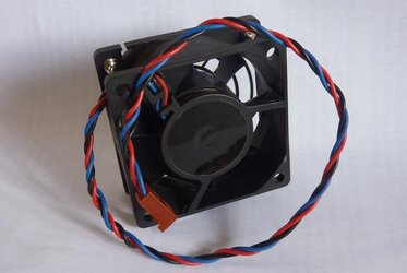
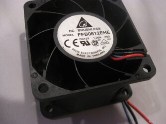
Pictures of a dead industrial high speed fan Delta FFB1212EHE.
Got it from a friend, there was an accident caused by a big screw driver dropped straight into the fan when it was rotating at full speed inside a HP Proliant server.
Two of the blades gone instantly.

Looks like someone was trying to dismantle it by prying the circuit board from the fan hub "brutally".
Actually the "right" way to disassemble a ball bearing fan is quite easy, just by taking off that little black clip at the middle of the shaft. Watch that small little black clip detached and placed near the center of the hub.

The other side of the fan, without the impeller, a 4 poles stator.

The fan's frame with all it's internal parts detached.

The impeller, with the small spring at the bottom of the shaft for holding back the ball bearing (not pictured here).

The inner view of the impeller, the outer plastic blades part is attached firmly to the big steel frame, and covered internally with the thick black magnet circle, also the embedded brass ring at the center to hold the shaft.

The other side of the impeller, a nice and strong bond between the metal body, brass ring and the steel shaft.

The view of the front ball bearing and with the small black clip detached, looks eerie.

Two ball bearings and the clip. Yep, if you can read the small label text at the right one, they're made by NMB, which is also a well known fan manufacturer, formerly called Panaflo.

The darkened area inside the brass tube is the 1st bearing location.

The 2nd location for the 2nd bearing at the other side in the brass tube.

Positions of the two bearings at the shaft when installed.

With the securing clip installed to show the very simple yet effective locking mechanism for the impeller to the fan's frame. All ball bearing fans are secured and locked like this.

The main board, you don't need to be an electronic guru to recognize this high speed PWM fan (4 wires) does have many electronic parts there. Ordinary 2 or even 3 wires classic fan usually have much-much less components, hence its way cheaper than their 4 wires brethren.

The other side, 4 poles with the copper windings, there are two big high power transistors under the stator and few other components. Fyi, most low powered 3 wires fan doesn't have many component installed at this side of the board, usually only a piece of component called the hall sensor.

The power transistor, a high power mosfet P type and made by IRF with part number -> IRF9530N, both are identical.
For those who understand electronic, its obvious from this mosfet alone, this fan can not be properly undervolted to slow it down, as they will not work properly when the supplied fan's voltage is at relatively low like 5 volt, like driven from common voltage control fan controller.
PWM control signal through the pwm wire is the only way to control the speed properly and efficiently for this kind of fan, mosfet needs proper volt to work.

Final pic, so which part of this dead fan can be useful ?
Ok, this should be easy, a nice and strong 38mm thick fan shroud.


Thats all, hope you enjoy this pictorial.
.
-
Pictures of a dead industrial high speed fan Delta FFB1212EHE.
Got it from a friend, there was an accident caused by a big screw driver dropped straight into the fan when it was rotating at full speed inside a HP Proliant server.

Two of the blades gone instantly.
Looks like someone was trying to dismantle it by prying the circuit board from the fan hub "brutally".
Actually the "right" way to disassemble a ball bearing fan is quite easy, just by taking off that little black clip at the middle of the shaft. Watch that small little black clip detached and placed near the center of the hub.
The other side of the fan, without the impeller, a 4 poles stator.
The fan's frame with all it's internal parts detached.
The impeller, with the small spring at the bottom of the shaft for holding back the ball bearing (not pictured here).
The inner view of the impeller, the outer plastic blades part is attached firmly to the big steel frame, and covered internally with the thick black magnet circle, also the embedded brass ring at the center to hold the shaft.
The other side of the impeller, a nice and strong bond between the metal body, brass ring and the steel shaft.
The view of the front ball bearing and with the small black clip detached, looks eerie.
Two ball bearings and the clip. Yep, if you can read the small label text at the right one, they're made by NMB, which is also a well known fan manufacturer, formerly called Panaflo.
The darkened area inside the brass tube is the 1st bearing location.
The 2nd location for the 2nd bearing at the other side in the brass tube.
Positions of the two bearings at the shaft when installed.
With the securing clip installed to show the very simple yet effective locking mechanism for the impeller to the fan's frame. All ball bearing fans are secured and locked like this.
The main board, you don't need to be an electronic guru to recognize this high speed PWM fan (4 wires) does have many electronic parts there. Ordinary 2 or even 3 wires classic fan usually have much-much less components, hence its way cheaper than their 4 wires brethren.
The other side, 4 poles with the copper windings, there are two big high power transistors under the stator and few other components. Fyi, most low powered 3 wires fan doesn't have many component installed at this side of the board, usually only a piece of component called the hall sensor.
The power transistor, a high power mosfet P type and made by IRF with part number -> IRF9530N, both are identical.
For those who understand electronic, its obvious from this mosfet alone, this fan can not be properly undervolted to slow it down, as they will not work properly when the supplied fan's voltage is at relatively low like 5 volt, like driven from common voltage control fan controller.
PWM control signal through the pwm wire is the only way to control the speed properly and efficiently for this kind of fan, mosfet needs proper volt to work.
Final pic, so which part of this dead fan can be useful ?
Ok, this should be easy, a nice and strong 38mm thick fan shroud.

Thats all, hope you enjoy this pictorial.
.


