I'm thinking of making a circuit to run an astable 555 connected to my motherboard RPM sensor, but i'd like it to only send a signal when it's light.
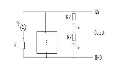
I came up with an idea but I can't think what to use where the "?" box is.
So for example when it's light the voltage between R1 should be quite high (maybe 7-10v) and when it's dark the voltage should be low (maybe 1.5 to 3V) . I'd like this to be able to trigger the "output" voltage to be 12v when it's light and 0V when it's dark. The output line should be capable of running a 555 circuit. The output needs (possibly) to stay at high voltage for weeks on end, or stay at a low voltage for weeks on end.
(Maybe R1 and the photoresistor need moving, not sure...)
Unfortunately i'm a bit of a novice at this so don't know what to use really.
Attachments
Last edited:
