I know *how* to do the volt mod, but am having some trouble applying it.
I have followed the volt mod instructions as shown HERE
I have soldered the connections securely, and have fired up the machine without the card dying - I get an image on the screen, and everything looks dandy.
Here's where the trouble starts. Using my multimeter to read the card's core voltage from the read point, I get a reading of 1.7V before the mod is installed, and 1.75V - 1.77V after the mod is installed. The problem?
Turning the trimmer has almost no effect on the voltage readout. If I turn the trimmer far enough to get a 1.77V reading from my multimeter, I get horrific artifacting in 3DMArk 01, as well as vertical and horizontal patchwork lines in 2D windows. Obviously the mod is working, but it's going to be a hard trip if I can't tell how much voltage I'm feeding the card!
Raising the trimmer's resistance to a full 10K Ohms still gives me a 1.75V reading. I removed and measured the trimmers resistance at the point where it gave me a 1.77V reading, and the resistance read as 5K Ohms - a dangerously low resistance that would be overvolting the core by a good deal.
I have removed the voltage modification at this point. I removed and reinstalled it *four times* to make sure my connections were good, and my nerves are totally shot at this point. All the installations started to show artifacting as I lowered the resistance of the trimmer.
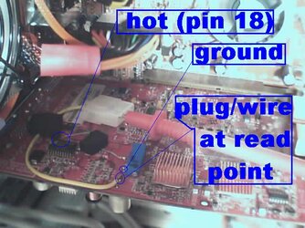
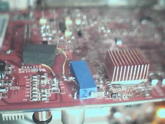
Below is a picture of one of the mod installations.
I have followed the volt mod instructions as shown HERE
I have soldered the connections securely, and have fired up the machine without the card dying - I get an image on the screen, and everything looks dandy.
Here's where the trouble starts. Using my multimeter to read the card's core voltage from the read point, I get a reading of 1.7V before the mod is installed, and 1.75V - 1.77V after the mod is installed. The problem?
Turning the trimmer has almost no effect on the voltage readout. If I turn the trimmer far enough to get a 1.77V reading from my multimeter, I get horrific artifacting in 3DMArk 01, as well as vertical and horizontal patchwork lines in 2D windows. Obviously the mod is working, but it's going to be a hard trip if I can't tell how much voltage I'm feeding the card!
Raising the trimmer's resistance to a full 10K Ohms still gives me a 1.75V reading. I removed and measured the trimmers resistance at the point where it gave me a 1.77V reading, and the resistance read as 5K Ohms - a dangerously low resistance that would be overvolting the core by a good deal.
I have removed the voltage modification at this point. I removed and reinstalled it *four times* to make sure my connections were good, and my nerves are totally shot at this point. All the installations started to show artifacting as I lowered the resistance of the trimmer.
Below is a picture of one of the mod installations.

")