• Welcome to Overclockers Forums! Join us to reply in threads, receive reduced ads, and to customize your site experience!

Question about modding Fedco 2-342 core

Overclockers is supported by our readers. When you click a link to make a purchase, we may earn a commission. Learn More.

HiProfile

Member
Joined
Dec 5, 2001
Location
Random Dumpster/Alley
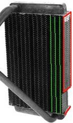
I was wondering about the side fins of the Fedco 2-342, the single-pass heater core for a Suburban. Looking at the attached picture, can side fins be cut off a bit as shown via Photoshopping it? I'm assuming the tubes are only between rows of fins (green lines) and not on the sides, equaling 13 total?

The reason why I ask is because I'm now considering changing my idea to put the radiator in the bottom of the case laying down. I want to use a single pass core, and had my mind set on a Bonneville core (and modding it to single-pass) since it's *just* within my max width dimention of 5.625". The problem with it is that its too long compaired to the Fedco 2-342 core, but the Fedco 2-342 core's prob is that its 6.125" wide. Each fin section seems to be ~.4" wide, so I'm guessing I could get just enough clearance if I shave those fins off both sides.

Can this be done?


ps: I already know a chevette core & expensive aftermarket rads would fit, but I don't want to use them.
 

Attachments

  • 338core.jpg
    338core.jpg
    24.7 KB · Views: 184
Err..this is a heater core. Technically there are no tubes. in a radiator the water flows through tubes wilth fins soldered @ a 90 degree angle. In a heatercore the fins are the tubes. so cutting them would irreparably damage the water channels. I'm stating this based on what i 've recently learned so someone correct me if i'm wrong.
 
Thanks greenman100. em00guy, if the fins on a heater core flow water through them, what are the extremely thin metal pieces that form the wavy pattern between the pathways the water runs through called? I think we just weren't looking at the picture in the right orentation or have different definitions. Basicly what I was asking was if any water flowed through the left and right sides of that picture - is there another water pathway to the right of that rightmost green line that would prevent me from removing the very thin fin material to narrow (as in go from 6.125" to under 5.875" wide)?

I don't mind if there's lots of metalwork ahead, I've done more than my share of metal cutting. You should see my R/C monster truck - I machined the steering assembly, the chassis, 4-link suspention, etc. As long as I don't have to solder shut one of the water passages (aka long individual 'cores'), I'll be fine. Its just been so long since I've done that to old radiators.
 
you probably know bwtter thatn my i've never actually seen a heater core i'm just going on what i learned on the forums in the last 2 days
 
HiProfile said:
Thanks greenman100. em00guy, if the fins on a heater core flow water through them, what are the extremely thin metal pieces that form the wavy pattern between the pathways the water runs through called? I think we just weren't looking at the picture in the right orentation or have different definitions. Basicly what I was asking was if any water flowed through the left and right sides of that picture - is there another water pathway to the right of that rightmost green line that would prevent me from removing the very thin fin material to narrow (as in go from 6.125" to under 5.875" wide)?

I don't mind if there's lots of metalwork ahead, I've done more than my share of metal cutting. You should see my R/C monster truck - I machined the steering assembly, the chassis, 4-link suspention, etc. As long as I don't have to solder shut one of the water passages (aka long individual 'cores'), I'll be fine. Its just been so long since I've done that to old radiators.

you'll need to do metalwork on the tanks

water flows through the long skinny flattened tubes

not the paper thin fins
 
see thats why you don't listen to newbs. And I apologize for my butchered spelling above.
 
Trust me on this... I've destroyed quite a few of these exact cores and I'm quite familiar with their internal construction.

The internals are tissue paper thin. The zig-zaggies in between the tube (which are extremely fragile) act as structural support for the said tissue paper thin metal. If you can manage to de-solder only the three outer tubes without burning a hole in the copper, then modify the end tanks without damaging the internals, and solder everything back together without a leak... You are a GOD
 
UberBlue said:
The internals are tissue paper thin. The zig-zaggies in between the tube (which are extremely fragile) act as structural support for the said tissue paper thin metal. If you can manage to de-solder only the three outer tubes without burning a hole in the copper, then modify the end tanks without damaging the internals, and solder everything back together without a leak...

and

UberBlue said:
You are a GOD
(sorry I couldn't resist :p )


All I need is to remove about 1/8" off each side, and each set of 'zig-zaggies' is about 0.4" wide (FYI "width" is the 6.125" dimention in that picture). The revised picture I'm posting highlights my area of greatest intrest, which is the boxed in red area - effectively the far sides of the finned area. Is that red zone a water tube/capillary/core/(whatever term you use), or is that just solder/bonding agent holding the edge of the zig-zaggies together?

If nothing else, all I need to do is grind away 1/8" of the zig-zaggy fins on both sides, or bend them down/push them in that far. If soldering is required, I'm prepared - I've 'sweated' lots of copper fittings at work already for people, as well as soldered up individual cores (capillaries/tubes) in several old Pontiac and Chevy V-8 radiators for racing (new ones cost $250USD). The worst one took 5 hours...but tested up to 18psi no leaks.

If I don't get the answer I want, I'll just go to autozone and ask to see the core. I greatly appreciate the help you've all given, its just that I can't think of a very clear way to ask the question.


edit: opps, forgot the picture...
 

Attachments

  • 338core1.jpg
    338core1.jpg
    8.6 KB · Views: 132
Last edited:
HiProfile said:
All I need is to remove about 1/8" off each side, and each set of 'zig-zaggies' is about 0.4" wide (FYI "width" is the 6.125" dimention in that picture). The revised picture I'm posting highlights my area of greatest intrest, which is the boxed in red area - effectively the far sides of the finned area. Is that red zone a water tube/capillary/core/(whatever term you use), or is that just solder/bonding agent holding the edge of the zig-zaggies together?

the "Red Zone" in your pic (i.e. the outer side that does not rin into the tanks) caries no water afaik .....
 
I decided to take the risk & order the heater core. After looking it over, I decided it could be done. The only problem I had was while deburring - the razor knife cut into the top, creating a hole... I ended up soldering it up (and all 3 other edges to be safe), and AFAIK there's no other leaks. In the end I got exactly what I wanted - a single pass core that'll fit laying down in the bottom of my Lian-Li PC-60 :attn:

I'm going to start modding it more (dual inlet/outlets) and do some cool things with copper fittings. My only problem now is the solder I have atm - Oatey Safe-flo silver, which IMO is fairly crappy (fraction of silver and large pasty range).
 

Attachments

  • Core01a.jpg
    Core01a.jpg
    39.3 KB · Views: 59
  • Core02a.jpg
    Core02a.jpg
    20.6 KB · Views: 54
Well the 2-342 heater core comes single-pass out of the box. All I did was to narrow it down so it'll fit. A single-pass heater core will be less restrictive than a dual-pass. Also, you won't have hot water tubes transfering some heat over to the next row of cooler water tubes.

ATM I have 2 more holes drilled into it, 1 per tank. Due to space restrictions I need to have a sharp 90degree elbow right after the pump into the rad. I figured I could merge 2 elbows to make a Tee (that flows better than a regular Tee) and, since the flow is split roughly in half, the elbow into the tank wouldn't sap much flow at all. FYI each extra hole is about 2.5" from the other, meaning if the rad was folded in half you'd have all four holes in a line evenly spaced. It'll all make sense once I post more pics. The prob is I accidently cut the wrong ends of the streeted elbows to make the Tee...
 
Back