• Welcome to Overclockers Forums! Join us to reply in threads, receive reduced ads, and to customize your site experience!

LED wiring

Overclockers is supported by our readers. When you click a link to make a purchase, we may earn a commission. Learn More.

BlueBall

Member
Joined
Feb 1, 2003
Location
The Hammer, Ontario
I am looking to wire about 40 LEDs in a row (in parallel) and I was wondering if I need to put any resistors along the row, or if the single 400R at the beginning of the 12V row is enough?

Will voltage drop (eight feet = 40 x 3mm LEDs @ 2" apart) make the first and the last LED have a different brightness?

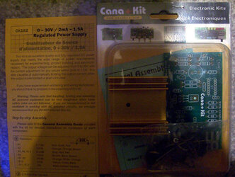
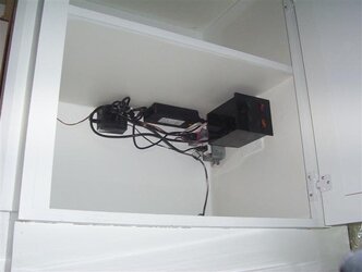
OR ... will a 'wall wart' supplying 3.6VDC with approx 500ma be enough (without the 400R)

recommendations please ....


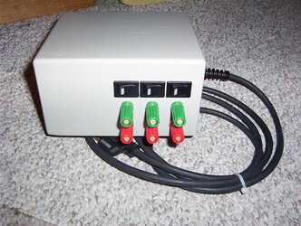
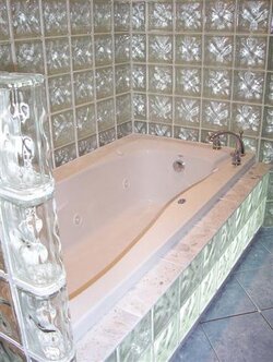
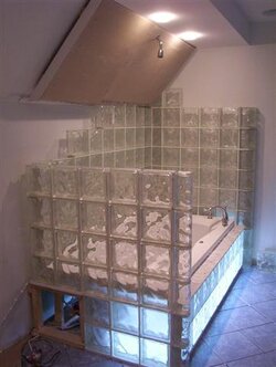
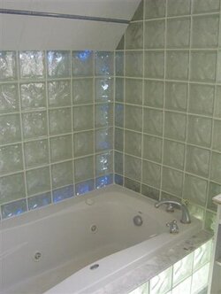
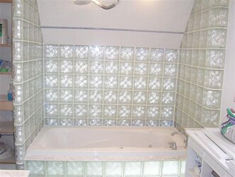
I will post a pic when I am done ... I am lighting behind 8" glass blocks that surrounds a jacuzzi. I am making flexible strips of bright LEDs that slide into clear acrylic tubing behind the glass. Custom design.

I know they make X-mas light 'ropes' but the light is yellowish. Too bad because they are $6 .. LOL
 
Last edited:
Here is what I would try:
I would buy 40 pieces 5V ultrabright sunbeam leds and hook them all up in parallel.
These leds are extremly bright and are designed to be hooked directly to a 5v source without any resistor.

As I said "This is what I would try". I have no clue if it would actually work, but I belive it would... They each draw 6-12.6 mA depending on what color you choose. Worst case scenario=40x12.6(red led)=506mA.... Someone correct me If my calculations are wrong.
 
Since you're wiriring them in parallel, placing a single resistor right after the battery (or whatever your powersource will be) will work fine. Also, because of them being wired in parallel, each LED will be equaly bright all down the chain. The only voltage drop that would cause the "end" LEDs to be dimmer should come directly from the wires.... Which at 0.01 ohms/foot (for 20 gague copper) would need a LOT more than 8 feet to make any difference :D

I'm not sure about the wall wart, though I'd be willing to bet it'd work fine provided they'll work with 3V.

JigPu
 
Thanks for the great info! You answered my question.

I ran out and bought this 5V 3A switchable power supply. I also bought resistors (82R). The entire circuit will be on a motion sensor. I also bought a humidity sensing exhaust fan.

Now I just need some bulk LEDs ... back to eBay ...


Thanks again .. I'll post a pic in a couple weeks :>
 

Attachments

  • Picture 041 (Small).jpg
    Picture 041 (Small).jpg
    58.9 KB · Views: 225
I believe there is a website that sells LED's from Hong Kong for like $1 per hundred or some excessivly low price. I'll see if I can track it down for ya.
 
Heres a pic of the lighting ....

I still need to get a shot of my led strands that are between the glass blocks and the back wall.
 

Attachments

  • Picture 006 (Small).jpg
    Picture 006 (Small).jpg
    39.3 KB · Views: 209
whoa! very nice. Although instead of LED's you could have used other methods of lighting up the base (incadescent lights or other stuff with a blue filter). Must of took you quite a long time to wire up all those LED's too.
 
Dc5e said:
whoa! very nice. Although instead of LED's you could have used other methods of lighting up the base (incadescent lights or other stuff with a blue filter). Must of took you quite a long time to wire up all those LED's too.

The base has a 4" flourescent fixture built in as well. That is what you see in the picture. The LEDs are there as well. They cannot be seen individually behind the white diffuser exept for the blue LEDs.

What else turned out to be really cool was the tile ledge was made of cultured marble and quartz ... sliced and polished ... the light shines up through the glass blocks illuminates the quartz embedded in the marble.

I'll add picks soon ... I just need to attach the cabinet doors and its basically done.
 
I learned a few things I'd like to share.

All power supplies are NOT created equal. Unfortunately, they do not label them properly.

Regulated power supply means there is exactly the labeled output. :thup:
Unregulated power supply means there is MORE than the labeled output
:bang head
The only way to tell them apart is to use a voltmeter.

I decided to make my own power supply from an educational kit.

I should learn alot from this.
 

Attachments

  • regulated power supply kit overview.jpg
    regulated power supply kit overview.jpg
    57.4 KB · Views: 192
Heres a new pic of my custom made low voltage control center.
 

Attachments

  • Glass Block Bath near complete 019 (Small).jpg
    Glass Block Bath near complete 019 (Small).jpg
    26.5 KB · Views: 160
Back