• Welcome to Overclockers Forums! Join us to reply in threads, receive reduced ads, and to customize your site experience!

DIY subwoofer building tutorial

Overclockers is supported by our readers. When you click a link to make a purchase, we may earn a commission. Learn More.

Ryan T

Member
Joined
Mar 1, 2003
Location
Mechanicsburg, PA
This is a basic tutorial on subwoofer design using a free program called winISD. You will need to download and install winISD http://www.linearteam.dk/default.aspx?download=winisd .

Ok lets start off by explaining some of the basics. The audible frequencies range for humans is 20 to 20,000Hz. A subwoofer is a special speaker that handles all of the low bass frequencies in a sound system. They usually handle the frequencies from as high as 150 Hz and lower. This is a great page for seeing what instruments cover what frequency ranges http://www.psbspeakers.com/FrequenciesOfMusic.html.

A standard powered subwoofer is comprised of a few different parts. The main parts are the actually subwoofer driver, an enclosure for the driver, and amplifier, and a crossover.

I'll start with the driver first. The subwoofer driver is what reproduces the bass. Most subwoofers will use 10" or larger drivers to hit the lower bass notes. I will be using a Dayton DVC 12" subwoofer driver for the tutorial.


Now onto the enclosure. The enclosures purpose is to isolate the back wave of the subwoofer driver. There are several different ways to go about building an enclosure such as using sono tube (large diameter cardboard tube's) or the more traditional wood enclosure. There are also quite a few configurations ranging from sealed to passive radiator to ported etc. We will concentrate on only sealed and ported.

Now lets talk about amplifiers. There are largely two ways to go about powering your subwoofer. One way is to buy a plate amplifier designed for a subwoofer. The other is using a normal pro audio amplifier (you can use old stereo receivers etc but those are really not ideal solutions). The most convenient in my opinion is the plate amplifier option since it usually includes the crossover and mounts right in the speaker enclosure. It is most cost effective and should provide plenty of power for most subwoofers.

Then there is the crossover. The crossover separates the the frequencies so that the subwoofer doesn't receive any of the high frequency material. You can buy external crossovers or if you buy a plate amplifier it will usually have a crossover built in. Most subwoofers are crossed over at 100 hz or lower. Your actual crossover point you would use depends on your main speakers and the room the sound system is in.


Now that we have covered some of the basics lets start by setting a budget for the project. Most good subwoofers will cost around $200~300 minimum but it can be done for cheaper. once you have a budget set you can start seeing whats available around that price point. I would recommend looking at Parts Express, or madisound (I like their Dayton Audio DVC and Titanic series, as well as Tang band products but there are TONS of great options out there). As mentioned earlier I will be using a Dayton DVC 12" subwoofer for the tutorial.

They are a very good value for performance and can work well in larger or smaller enclosures. Once you have a driver selected you will need to get the T/S parameters do design the enclosure with winISD. This is a great page for learning about subwoofer design and they have a good explanation of T/S parameters etc. http://www.diysubwoofers.org/define.htm . Those companies I listed above usually provide the T/S parameters for their drivers. Each driver is different from the next so to model how it will perform we need those specifications. Se lets look at the 12" dayton DVC subwoofer driver. The T/S parameters are supplied in the description.

Specifications:
Diameter 12"
Power handling: 350 watts RMS/per coil, 700 watts max
Impedance: 8 Ohms
Frequency Response: 20-450 Hz
Sensitivity: 87.4 dB 1W/1m
Voice coil diameter: 2"
Magnet Weight: 112 oz

T/S Parameters
Resonant Frequency (Fs): 22.2 Hz
DC Resistance (Re): 2.8 ohms
Voice Coil Inductance (Le): 1.76 mH
Mechanical Q (Qms): 8.69
Electromagnetic Q (Qes): 0.4
Total Q (Qts) :0.38
Compliance Equivalent Volume (Vas): 4.25 ft.³
Mechanical Compliance of Suspension (Cms): 0.2 mm/N
BL Product (BL): 15.85 Tm
Diaphragm Mass Inc. Airload (Mms): 259.3g
Maximum Linear Excursion (Xmax): 15.1 mm
Surface Area of Cone (Sd): 502.7 cm²

Now you'll need to open winISD and we can start modeling an enclosure for that driver!

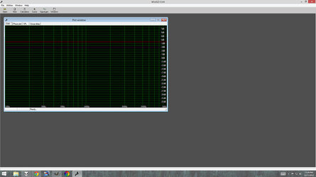
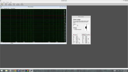
When you first open winISD you should get a screen like this.
11334159335_31f71b83d4_b.jpg


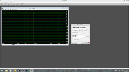
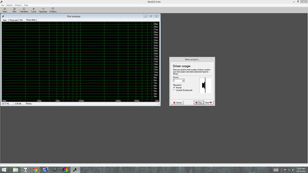
You will need to click on the New icon to start a new project. A new window should pop up like this.
11334253524_10b5ce8135_b.jpg


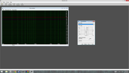
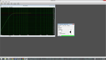
Next you will need to click the new button to the left of driver name to open the Driver Editor.
11334253454_cb509fb49f_b.jpg
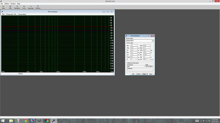
Now lets name the driver Dayton DVC (dont include numbers in the driver name. for some reason they wont get saved if there are nubmers in the title). Then fill in the Driver data boxes with the correct value as givien for that specific driver. Sometimes you need to set winISD to the proper measurement system. For instance Vas will usually be measured in liters or cubic ft. To change winISD Just click the mouse over the measurement system to the right of the box and click it until you get the correct measurement system.

It should look like this when you are done.
11334159595_67f4900a6c_b.jpg

Sometimes you will not have a value like BL or Sd. Its usually ok since we are just modeling the enclosure. Once you have all the values filled in click the OK button and then Close. That will close out the window bringing you back to were you started.


Now click new again. this time select the Own drivers under the Load drivers from: Also click the show driver parameters check box.
11334227956_583f31beae_b.jpg


Now click next and it should bring you to the driver usage screen. Here you can select how many drivers to use and their configuration. We will be just using one driver and it wont be iso-barik so just hit next.
11334217485_e3354f8c83_b.jpg

Continued------
 
Last edited:
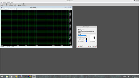
Now that should bring you to the Box type menu. The blue bar shows you which alignment the driver is most suited for. It doesn't mean it wont work in either situation but its just a rough guide. Now this is were you can start to make some more decisions about the subwoofer. I will concentrate on just vented and sealed. This is were you will have to decide what the subwoofer will be used for and what type of sound quality your going to try and get from it. Sealed enclosures are usually cleaner and smaller than ported. But they will not be able to achieve the same levels of SPL or extension as ported. Some of you may be asking what a ported enclosure is. Well a ported enclosure has a tube (or slot vent in some cases) which tunes the enclosure to a certain frequency. There are various draw back and advantages to ported enclosures. But as a general rule of thumb ported subwoofers are better for movies and games while sealed subwoofers will be better for music. I wont go into to great detail on which is better for what but there is a lot of info on the web regarding this.
11334324816_76c69e11b2_b.jpg


Now once you have decided which type of enclosure your going to use click the finish button.
11334159265_86f5c381ab_b.jpg

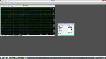
A new windows should pop up with five tabs; Driver, Box, Vents, Plot, Project. Now I'm going to design a Home theater subwoofer. I'm going to shoot for deep extension and a low tuning point. So click over to the box tab. Now winISD usually defaults to the a good tuning point and enclosure size for the driver. One of the big things you will hear a lot about is the F3 of the subwoofer. F3 means the point at which the subwoofer is -3 dB down (were it's response starts dropping off basically). winISD has two bars along with the plot of the driver in its enclosure. The red bar is the 0 dB line and the purple bar is the -3 dB line. You can click and hold the left mouse button in the graph window and move it left and right to whatever frequency you want. it will will tell you what dB the subwofer is at that frequency. You can tweak that to different specs though. For instance if the enclosure is too big for you. You can make it smaller and work with the tuning point to see how low it will go. You want to aim for a flat response as low as you can. With the 12" DVC about the best you ca do is a F3 of around 22 or so Hz. 11334227906_c081aec256_b.jpg


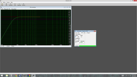
Now to find the proper vent length and diameter click on the Vents tab. Here you can enter the number of vents you want to use and the vent diameter. It will calculate the length needed for those vents based on the enclosures internal volume and the tuning frequency you set over on the box tab. You need to make sure that the Vent mach number stays green. If it goes red that is an indicator that you will have some port noise from your subwoofer. Basically it means that at higher volumes you will hear kind of a wind noise cause the port is too small. I like to try and keep the number below .10 . Some things you can do is buy flared ports which cut down on wind noise a LOT.
11334253374_330f106099_b.jpg


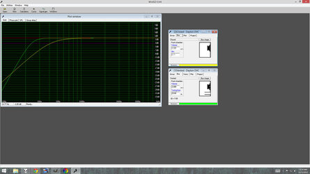
Now for a bit of comparison work lets check out how the sealed 12" DVC would look compared to the ported enclosure.

Leave the Vented DVC window open and click the new button in the menu to start another subwoofer project. follow the same steps except as above for the vented subwoofer when you get to the Box type window select closed and hit finish.
11334298413_9e30c288f3_b.jpg


Now it shows you a comparison of both system vented and sealed. As you can see there response is very different. The sealed starts rolling off much faster and doesn't extend nearly as low as the ported. Now flip over to the box tab on the Closed dayton window. You will notice that there is no more tuning frequency window. You only have volume and Qtc. Here is a great page explaining what Qtc is http://www.diysubwoofers.org/sld/sealed1.htm . I would normally not pick a Qtc of above .707 but thats just me. If you like more of a thump and boom sound the higher Qtc values will give you that. The lower values are the most transient and have the lowest group delay. For this sealed subwoofer I'm going to make the box 3.171 cu Ft for a Qtc of .57


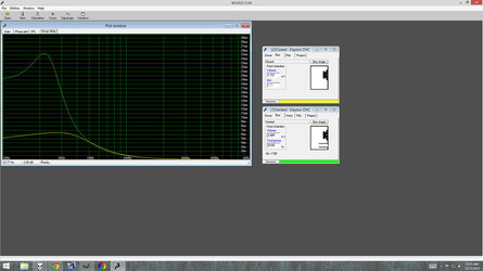
now you may be saying, if the ported subwoofer goes so much lower and louder why would you even build a sealed subwoofer? Well the reason is sound quality. If you switch over to the Group delay tab in the Plot window you will see what I'm talking about. See how much higher the delay is for the ported enclosure? The group delay peak is highest at tuning frequency. This can lead to a "slower" or more boomy sounding bass.
11334227876_12cf316940_b.jpg

continued--------
 
Last edited:
The reason I like to tune subwoofers low is beaucse the group delay is highest at the tuning point. So if you tune it to say 30 Hz for max SPL at that frequency you will also have that huge group delay spike at 30 Hz. So in my opinion I like to sacrafice a little spl up higher for lower flatter bass with as little group delay spike in the upper bass regions as possible. Another factor is that frequecies below the tuning point unload the driver. So if you tune it to 30 Hz the driver will have a very good chance of bottoming out below that tuning point. The enclosure for a driver provides a cushion for it if you will. So below the tuning point there is no (or very little) cushion. So for home use tune it low :D ! If you do tune it higher the only thing you can do is either limit the material going to the subwoofer to stuff without contnt below the tuning point or install a rumble filter. A rumble filter is kinda like a crossover that cuts out the lowest frequencies of the subwoofer. I beleive the Parts Express plate amp has one at 18 Hz so it starts cutting all the frequencies below 18 Hz. If you want to look into designing one I would just try and search around on google. I really dont have much info on then or their design :). So sealed enclosures also have that advantage over ported. They have the lowest group delay and the do not unload below the tuning point.


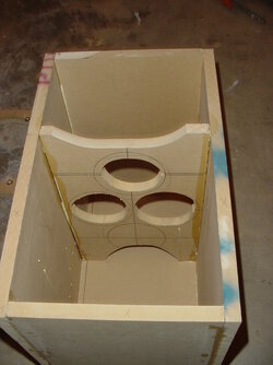
The next thing we'll talk about is enclosure bracing. Once you put a driver in an enclosure and play music or movies through it you can set your hand on the enclosure and feel that it is vibrating. Idealy you would want no enclosure vibrations but you will almost always have to settle for some. One way to conqueror some unwanted vibrations is to brace your enclosure. There are a ton of different methods for bracing. Some people use shelf braces or crossbraces. Some use dowel rods or 2x4's etc. There really is no right way to do it. There is a simple but very effective rule of thumb and that is dont leave a wider than 10" panel span inside the enclosure unbraced. As you can see if you have a large enclosure that is a lot of bracing. Most people will not put that much into it but I think at a minimum you should have something like a shelf brace. Here are two examples of shelf braces.
11334459813_1bf015cfab_b.jpg


11334325495_67d89c82cf_o.jpg


These are examples of two ways the using a shelf brace. The first one runs from front the back of the enclosure. The second one is from top to bottom. Both work well but ideally you would want to install another brace perpendicular to the brace in the first picture. That would be a full cross brace. If you are using boards for the brace make sure to cut air flow holes in them!
Now another topic that comes up is construction materials. I use 3/4" and 5/8" MDF (medium density fiberboard) for my enclosures. Some people like to use no void plywoods like baltic birch but they are more expensive. A standard sheet of 3/4" MDF is 4'x8' and will usually run you around $20. I would use no thinner than 3/4" for subwoofer enclosures. Another type of enclosure is the sono tube subwoofer. They use big thick compressed cardboard tubes. The sono tube was made to be the cement pillar forms for buildings but it also works great for subwoofers. You just cut it to the desired lenght and make two endcaps from MDF or baltic birch. The sonotube can be more expensive (its usually around $70) but its much easier to work with. For ports I have used flared and just standard PVC pipe. The flares are more expensive like these
http://www.partsexpress.com/pe/showdetl.cfm?&DID=7&Partnumber=268-352
They are very nice looking and there is less wind noise but either port will work (straight PVC pipe or flared).


That is really pretty much all you need to start messing with building a subwoofer. There are other things to consider like enclosure shape etc but that is really beyond this walk through. One thing that is very important is the graphs in winISD are NOT going to be how the subwoofer performs in room. Once you put the subwoofer in your room you will get some room gain (or a lot, it depends on the size of the room). The smaller the room the more the gain. You can read more about room gain here. http://www.diysubwoofers.org/sbc/sbc3.htm . I know I linked to Diysubwoofers.org a lot but they really have a great site that is explained very well and i highly recommend browsing around over there for some great info. My main goal with this tutorial was to show you how to use winISD to design an enclosure for a subwoofer.


Now I know this was really just a basic overview. There is a LOT more to building subwoofers than what is covered here but most of the stuff is really case specific. Like how much bracing and were to put it in the enclosure etc. Also driver selection can have a HUGE impact on how the subwoofer sounds and how large the enclosure is going to be. Some really good drivers are Adire audio Shiva or tempest, and the Dayton audio (parts express) 12" and 15" DVC. They work well in ported and sealed enclosures. The 250 watt plate amplifier I linked to works excellent and is a real workhorse.


One more thing I'd also like to touch on for a bit is subwoofer placement. This isnt part of the design or building process but were you place the subwoofer in your room can have a profound impact on the sound quality! There are different methods for finding the best placement but I've found that the best and easiest is to move the subwoofer into your seating area. If its at a computer desk move the chair and palce the subwoofer were you would sit. Then put on some music or movie with a somewhat constant bass line (test tone sweeps can work too). Turn on the music or moives with the subwoofer in your normal listening position and then crawl around the room and listen for the place with the best response. I know this sounds kinda crazy but it honestly works very well. Worst case scenario someone will walk into your room while you are crawling around and think your insane :D .

There are a few common things from room to room. The loudest position is usually in the corner. The subwoofer gets a boost in dB from having walls near it. In the corner you have the left, right and floor giving an SPL boost. The closer you are to the walls the more boos you get. But the corner is also were the frequency response may be the most erratic. Most of the time a good compromise fot SPL and sound quality will be placing the subwoofer along one wall of the room (towards the center of the wall). But subwoofer placement is very room specific so there is no universal perfect place for a subwoofer. You really have to find the right spot for your listening tastes and room.


Finally I want to talk about actually building the enclosure. There are plenty of great methods for building an enclsure and no really right or wrong way. I will explain the method I use from start to finish for subwoofer. I wont be posting any pictures for the subwoofer construction but you can check out the DIY discussion thread (I know its really long but there are a bunch of great projects in there) and there are a few other great threads that people have made detailing there build process for their subwoofers.


a few months back I made a subwoofer based from a 10" dayton titanic driver. It was going to be for games and other computer use. Since it was mostly for gaming I wasnt too concerned with sound quality so I went with a ported alignment.

I got the T/S params for the driver.
Power: 280w RMS/400watts peak
V.C. dia-2" V.C.
Le-1.9mH
Z-4 ohms
DCR-3.05 ohms
Fs-25.8
magnet weight-76oz
spl-90.2 2.83v/1m
Vas-2.37 cu ft.
Qms-8.09
Qes-.41
Qts-.39
Xmax-12mm
So I input those numbers into winISD and started the enclosure modeling process. I wanted the size of the enclosure to be around 2 cu ft. That was about the largest I was willing to go. So working with those size limitations I had roughly 1.9 Cu ft internal volume. So I went into winISD and started a new project using the titanic driver. I set the internal enclosure volume to 2.0 Cu Ft. I found that tuning it to around 26.5 Hz was the best response curve. It gave me an F3 of 27 Hz which would work great for games. So then I switched over to the vents tab I had in mind to use a flared port from parts express. It was 3" diameter and 11.5" long. Now as you can see from winISD that size barely works. It has a vent mach of .16 which is higher than I would like but winISD doesn't take into account the port flare so I risked it and went ahead with the design. With my enclosure dimensions picked out I had to do some simple math to plan the panel sizes for the enclosure. I wanted the enclosure to be as narrow as possible so 12" was the external width. I also wanted to get the port on the front of the enclosure below the driver. So 19" was the required hight. That left me with a 12" x 19" x 19" enclosure. You can find the cu ft of an enclosure by multiplying the width by the hight by the depth (in inches) and then dividing by 12 three times. Since the MDF is 3/4" thick I had 17.5" x 10.5" x 17.5" which equals 1.86 cu ft. Then all I had to do was measure the size of each panel to cut. The front and back were going to overlap the top bottom and sides. So it needed to measure 12" x 19". The top and bottom are totally inset so they were 10.5" x 17.5". The sides were inset with regard to the front/back and overlapped the top/bottom so they were 19" x 17.5". I needed some bracing so I went with a single shelf brace from front to back. It was the same size as the top and bottom piece.


So now that you have the panel measurements you can cut the pieces. I used a hand held circular saw (a table saw would be ideal). Just cut the pieces as clean and straights as possible. I made a guide for my saw out of a long metal level and some clamps. You can get pretty good results without a guide just make sure to take it slow and steady. When you have all the pieces cut move onto the gluing stage. But before gluing I like to dry fit the enclosure and see if your terminal cup or plate amp will be hitting any of the bracing etc. It is much easier to notch out a section of brace before its glued into the enclosure :). Once everything checks out mark the pieces so you know what goes were. The first pieces I glue are the sides to the top and bottom and brace. Before gluing just dust off the boards to make sure they are clean. Then apply a bead of glue to each side of the joining areas. Smooth out with your finger and clamp the boards in place. Wipe up any extra glue that may have seeped out with a damp rag. Let it dry for at least 30 minutes (for the yellow elmers glue. Read your glues label for drying time). Then set the back piece in place and mark were the terminal cup or plate amp will go. Cut the hole and test fit it. If the plate amp or terminal cup is hitting the bracing you may need to notch out a bit of the bracing. Once that is dry I glue the back piece in place and clamp it. I then let the enclosure dry overnight.
The next day dry fit the front board and mark were the subwoofer and port will be going. Then cut the holes out and test fit the driver and port. Make sure the driver and ports ill clear the bracing. Once you dry fit the front run a bead of silicone caulking over all the inside edges. Finally glue and clamp the front panel on and let it dry overnight. The last step is to caulk the as best as you can sound the front panel (usually thought the plate amp hole on the back and the driver hole on the front) and apply a bead of caulking around the port and tap it in place with a rubber mallet. Let the caulking dry for at least 24 hours!! silicone caulking leaks out gas while it cures. Those fumes can melt the glues used to hold together some drivers. So make sure it is fully cured before installing the driver. When its all dry your finished with the major construction. I go over the whole enclosure with sand paper and use wood filler for any areas were there are little gaps or were the boards dont meet cleanly. Then sand it all smooth and your ready to apply the finish. I wont cover the finishing process since there are so many different types.


I hope this has shed some light on subwoofer design. Again I would go over to www.diysubwoofers.org and read read read. That is a great place to get started and learn about all the basics. If you have any questions, comments, suggestion or corrections feel free to post them!


Ryan
 
Last edited:
wow, this is great... I used no bracing in my box since it was my first one. I hope it doesn't fall apart that fast... :D

But my second box will be much better becuase know I found out many things after I built it.

This should be a sticky!
 
The box should hold together fine. While bracing does help the enclosure strength it's biggest impact is on sound quality. So I wouldnt worry about the enclosure falling apart ;).
 
thegreek said:
wow, this is great... I used no bracing in my box since it was my first one. I hope it doesn't fall apart that fast... :D

But my second box will be much better becuase know I found out many things after I built it.

This should be a sticky!
It's been a sticky for most of the day :p

Edit: Fixed those image links for you.
 
Last edited:
I added a few things about subwoofer placement and enclosure building. Again if anyone sees any errors or has any comments on how to improve the walkthrough let me know!


Ryan
 
hey ryan, great turtorial, i forgot to thank you. i actually used it cuz winISD was giving me a hard time, after reading it, it all made sense :) i can see why its good to take the effort and do this, i've never had bass that sounds so good!!
 
Thanks for the complements guys :). I thought with all the sub building threads sprouting up the forum could use a tutorial on winISD. I'm glad it helped a few people out at least :D.

Theres more I could have done with it though. I didnt really try and explain picking a driver etc since its such a case specific thing but those links to diysubwoofers.org are a great place to get the info about how subwoofers work etc. I may try and explain some of the other aspects like go more in depth on enclosure building or driver picking later on.


Ryan
 
Ryan T said:
Thanks for the complements guys :). I thought with all the sub building threads sprouting up the forum could use a tutorial on winISD. I'm glad it helped a few people out at least :D.

Theres more I could have done with it though. I didnt really try and explain picking a driver etc since its such a case specific thing but those links to diysubwoofers.org are a great place to get the info about how subwoofers work etc. I may try and explain some of the other aspects like go more in depth on enclosure building or driver picking later on.


Ryan

yea diysubwoofers.org is great, i got most of the equations to calculate frequency according the the t/s info i had. definitly worth doing a little math work.
 
ryan, how do you plug your port?

For my Tempest sub I actually flip the tube upside down :D. I know it sounds kinda dumb but since the port is on top once the sub is flipped over the port fires into the carpet. Since the sub is fairly heavy nothing significant leaks out. You can really feel the resistance of the driver cone when the sub is upside down too. When the port is "unplugged" it moves very easy but once the the sub is upside down and the port is effectivly plugged it has much more resistance.

If that method doesnt apeal to you some people use nerf footballs or t shirts etc. If you have some closed cell foam you can cut a port plug that you can jam in there. The foam port plug is really the best solution. But the foam has to be pretty beefy and not let any air through.


Ryan
 
Can we have some pictures of the finished product?

Edit: How do you use and do you even need a crossover and/ or inductor.
 
Last edited:
You can check out my website for some pictures. The PC Sound System project has a few pictures of one subwoofer I've built. Other than that I build mostly sono tube subwoofers.

You do need a crossover for the subwoofer. However if you buy a plate amplifier it will usually have a built in crossover for you. I wouldnt use an inductor as a subwoofer crossover for two reasons. First it would be VERY expensive to get an inductor with a high enough value to cross the sub over low enough. And second if you just use an inductor it will only be a 6 dB per octave crossover slope. Meaning that a lot more of the higher frequency material will leak through to the subwoofer.

If you dont use a plate amplifier there are still options. Almost all home theater receivers have subwoofer pre outs that are crossed over. Ususally its a fixed crossover at 80 or 100 Hz but they work pretty well. You could also use an active automotive subwoofer crossover. It will run you around $30 for the crossover and a AC/DC adaptor but it works pretty well also.


Ryan
 
I built my own home sub and speakers years ago....I always remember waiting eagerly for the parts express and MCM catalogs...oooh i used to dream of those focal drivers, well, until I bought them :)
 
:) well its fully done and working really well
All baffeled and sealed. In a large room not in a corner or hard against the wall we were testing it and stuff was falling off the shelves
 
Back