• Welcome to Overclockers Forums! Join us to reply in threads, receive reduced ads, and to customize your site experience!

DIY Waterblock

Overclockers is supported by our readers. When you click a link to make a purchase, we may earn a commission. Learn More.

a1cnolan

Member
Joined
Oct 11, 2001
Location
georgia
Okay well its been about 2 years since i watercooled my first computer.

I loved the results and I loved building it. It was challenge the first time out but because I am a machinist by trade I was able to make a direct one to one copy of what is now called(i think) the RBX. you know, the one with the three barbs and the "micro-fins" in it. The thing worked great and i was rarely above 35C even when raising the voltages high.

Well I'm back to try my hand again at creating my own rig. I plan on buying one of the new Intel core 2 duos. I've never used intel and am unaware how mounting works on them.

The question i have is fairly simple. Can someone direct me in the direction of the best waterblock on the market right now that will fit the new Intel CPU's so i can begin making one and give me some ideas on how people are locking them down to the mother board.

I'm hoping to find time to make my own case for this with enough room to fit everything inside of it and to put the radiator, res, and pump in their own compartment so i can keep the heat from the rad and pump out of the mobo area.

I'm probably going to have extra copper left over to make extra blocks when im done so ill probably be selling em off for like 10 to 20 bucks each on ebay to try and recoup the money for the rig. No worries about copywrites. i don't plan on making a direct one to one i just want some good ideas for something that will work good and fit the new type of proc im using.
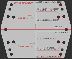
 
Here's them mounting hole specifications.
mh.gif
The Swiftech Storm, Swiftech Apogee, and White Water revisions are the top 3 right now. There are optimal dimensions for base thickness, channel wall thickness, height, and channel width that have been researched thoroughly in the past 2 years. Some of the most intricate designs I've seen involve EDM machining to create extremely thin and tightly packed fins.
 
Thanks for the input guys. I have questions pertaining to the holes for the block.

My preference would be to design the block so it connected straight to the board. What i mean is the last system i built required that i used either springs and/or a mounting clamp what i would like to do is machine it so the mounting holes touch the board. possibly with like a rubber washer to avoid the metal touching the board.

I'm looking at a picture of the P5W. It is a top down pic but it looks like there are mosfets in the way so i probably couldn't just make a big square with some legs going down to meet the board but i will be CNC machining this project so I could have legs come out of the main part of the block and then go down to the holes. Does anyone have the distance precisely from the top of the processor down to the board on an the 775 boards?

It's a lot to ask i know but im pretty sure it would save me a lot of time...

Also i was looking around the shop for metal for the block. The only copper we have on hand is 1/8" thick. So I'm gonna have to get a little crazy on this. My plan is as follows.

I will machine out the top of the block with the mounting holes and the barbs and everything. This will be 6061-T6 aluminum. Then i will slot out the bottoms side of that to either .250 or .375 depth. Then I'll machine three pieces of the .125" copper to fit in that slot with about a .004 press fit. Either one or two of these will have the a slot in them to create area for water to go through(i haven't determined if i want to maze it or fin it) and then the third one will be pressed in to follow those and to seal the innards of the block. I figure a .004" press fit should be strong enough to keep the seal.

Does this sound like it would work to you guys? i don't know if i explained it right. If you need clarification let me know.

Also if you guys have any input on how thick the base plate should be i would appreciate it. I can use any input you got because after all im just a machinist/ welder...not a physicist
 
Im not sure if the measurements your asking for wouldnt be better measured by you or someone with acess to micomiter type measuring divises for such a mounting project.

You might want to head over to the US pattent offices website for actuall measurements of blocks (since your making a knockoff just for your personal use there isnt any issues with that) heck with mounting like what your proposing integrated it might be a patentable product anway. (when applying you would just referance the pattent(s) that your block was based off of (and the ones they sited in there pattent submitions) and include the information for your integrated mounting solution, and the reasons that its better then the current solutions bla bla bla)
Pattent numbers shouldnt be too hard to find.
 
1. I wouldn't make the top out of aluminum unless you can get it anodized. Brass would be preferable.
2. Why would you need legs on the block top? You could just use longer nylon or aluminum spacers cut to length. Not all CPUs and sockets have the same height so you wouldn't want to design the top for just one.

3. For fitting the various parts together an o-ring is best. I personally prefer red-orange silicon O-rings because they compress further than Buna-N o-rings.

4. The optimal base thickness is 2mm. It gives the best balance of thermal transfer and material strength. The most feasible dimension for channel width is 1/16th (1.5mm), the optimal channel wall/fin thickness is 1mm, and the best channel wall/fin height is 3mm.

If you need help with CAD work or design selection let me know.
 
1)I don't have any copper for the top so i decided to go with aluminum because it is the most abundant material we have in my shop. I can't get it anodized but i do have some access to getting it alodined. Would that be a suitable substitute. Its what we do on the aircraft to prevent corrosion when dealing with two types of metal that will contact eachother.

2)Well i could do that. I would still have to make legs that come out to avoid hitting mosfets by using a regular square. Now I could get rid of the part of the leg that goes down towards the board and use some type of spacer but i was looking for an install that would have the least amount of loseable parts. I tend to be clumsy and drop screws inside my case. wingnuts and such. I didn't want to deal with springs either because i am in japan and asking a hardware store for compression ratings might as well be like asking for the launch codes from the president's "football" breifcase. I just wanted install and removal to be as easy as possible.

3) i could make the middle copper plate a smaller dimension and fit an o-ring around it when i place it inside the block but i don't see a pressfit of that magnitude coming apart for water pressure. I'll obviously have to pressure check it and then i can just try it with an o-ring after failure. I don't even have the pc yet so i have time to mess with it and get the best block i can make.

4) those dimensions are going to be tough because small cutters break really easily so we might not have any. The fin height will work because thats about the thickness of my copper and the thickness of the baseplate will be easy but im not sure if it will work for the purposes im trying to because of the pressure building on it.

good ideas. I like it I'll try and institute them. The mounting thing is the only thing that is bothering me now
 
1. Alodining should be perfect, and in fact would be preferable to anodizing in this application.

2. Ah I understand now. Yes it's quite common to trim the mounting plate down and for that reason some manufacturers simply offer a seperate mounting plate for LGA775 rather than including every mounting hole. To make the mounting easier you could use long bolts fed in from the rear of the motherboard and then have a sandwhich of parts as follows.

1. #6-32 Bolt head
2. nylon washer
3. motherboard
4. nylon washer
5. aluminum spacer
6. hex nut
7. waterblock top
8. knurled nut

That would make installation/removal a breeze and you'd never have to undo anything other than the knurled nut.

3. If the middle piece inserts into the top and the top is sealed to the base with an O-ring you'll be fine. Most waterblocks have a copper base with a total thickness of no more than 1/8" to 1/4". Then the remaining parts are of more inexpensive and easier to machine materials.
The channels are milled into the base and the the top and middle parts control the inlet and outlet flow patterns.

4. Indeed. You may have to step up to a slightly larger bit size to make things easier. I was only referencing optimal numbers, which are not always practical to obtain. I wouldn't use an end mill any larger than 1/8" to make the channels though.

In interested in seeing a conceptual image of your block design. Even if you make just a doodle I could help you refine your design in CAD this week.
 
Okay, I'll start drawing it up in featurecam and then take some screenshots of each part when im almost done...Then you can get a better idea of what I'm talking about.

Okay. One more thing...I am planning on using a Via Aqua 1300 pump. its like 370 GPH if i remember correctly. Now if i did micro fins how many would i have to put in there to make the optimum amount of water move through it? if the height was 3mm...do i want a whole lot of restriction or not?
 
Okay here is what i came up with while i was at work tonight
First the top of the top. And the second will be the bottom of the top.

What im thinking of right now is one .125" piece slotted and then pressed into the base and then the base plate at .080 to be pressed into that. with some sort of o-ring maybe. we will see
index.cgi


index.cgi
 
and then here is what i cam up with for the copper insides and the base plate that get pressed in and then the bottom gets lapped

index.cgi


So what do you think CapatainSlug...oh by the way on that slotted inside. The cutter is .125" the and distance between the centers of the groove is .188" so makes the walls .063" thick. not quite microfins but i won't break a buttload of cutters making it work.

Also the center is a .375 inside diameter hole and the periphs are .250. i figured that would be like the normal inside diameter of 1/2" and .375" hose barbs.

I'm hoping for good things out of this block but if you don't think enough water will get through we can make another one with more space for water to flow. shouldn't be too hard to mock it up
 
The channel walls are a little too thick, reduce the fins/walls to 1/32" thickness.
You will get better performance if you make them parallel fins rather then bending paths.

Mill the pattern into one piece rather than making it from two seperate pieces and trying to join them.

And there's no need to put a well in the center. The center needs fins the most. I also recommend going with 1/4" BSPP threading for all barb connections. NPT is a pain to work with and you won't need anything larger than 1/4".

I'll show you a CAD model of the revision I think will help performance and machining time later tonight.
 
Well the thing about it into one piece it that i don't have any stock thicker than .125". like i really don't.
The well in the center can go easily but should there be space above the fins for the water to flow over so it can get to the rest of the block? or should it just be a slot on the center with fins in it and not worry about the rest of the block?

as i said im limited on cutters so the smallest channels i can make are like .093" and i only have on ball end mill that size. so its gonna be tough. can't wait to see what kind of ideas you got. whatever makes it cool is cool
 
I have some scrap .25" x 2" bar if you need a chunk.
And effectively you want to try to cram all of the turbulent surface area into the very center inch to inch-and-a-half on the base and minimize potential restriction everywhere else.

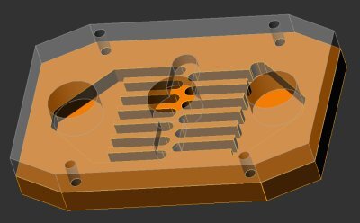
Here's the preliminary design I've come up with using 0.25" thickness material and a 1/8" end mill. I need to experiment with other patterns, but staggering the paths in some way produces the best results.
ac1_0.jpg
I'll figure out the O-ring groove later.

How thick are the aluminum scraps you have on-hand?
 
Last edited:
aluminum...i have pretty much whatever i need thats why i drew the hose barbs into the machining process. one less place to leak.

as far as aquiring 1/4" stock i just don't know. i live in japan so mailing it to me isn't likely. im waiting for a friend of mine to get back to me on whether or not hes got some.

I really don't care if it is fancy. just as long as it works.
anyway i gotta go to work for now
 
Well, do you have any silver solder and silver flux? Other than brazing that would be the only way of melding the two parts that would provide effective heat transfer from the base to the fins.
 
umm minor detail though, theres a good reason for the springs. they give adequate resistance to protect your mobo yet allow for adjustability which you need to get the right pressure depending on any variables which might lead the distance of you ihs or die to the mobo to be a bit off; this all being to get the optimum pressure for the greatest cooling power.
 
Yeah i was thinking about tinning the surfaces of the copper with silver sodder anyway to take care of that little detail. I could braze or silver sodder them. I figured the silver sodder would be better because it is softer and thus would press together and make a better bond.

Also I was thinking today of not only doing a press fit but dropping the copper in the nitrogen tank and putting the aluminum in the heat treating oven and trying for a press fit with a shrink fit. my only fear would be cracking the block with the added pressure. Also do you think 6061-t6 or 7075-t6? is there a bonus to either in terms of conductivitiy?

I pretty much have everything i need in my shop to make it work except the 1/4" copper.Its good to have this forum to go over all this stuff in advance.

oh. Also do i need space between the top of the block and the fins or should they meet eachother?
 
Back