- Joined
- Jul 5, 2004
- Location
- Toronto, Canada
Ok so I'm going to try and make a fan controller to adjust the speed of the following 6 fans;
Delta AFB1212LE 12V .19Amp 2.28W
Delta ASB0812HH 12V .20Amp 2.40W
Delta ASB0812HH 12V .20Amp 2.40W
Vantec SF12025L 12V .08Amp 0.96W
Vantec SF12025L 12V .08Amp 0.96W
Vantec SF12025L 12V .08Amp 0.96W
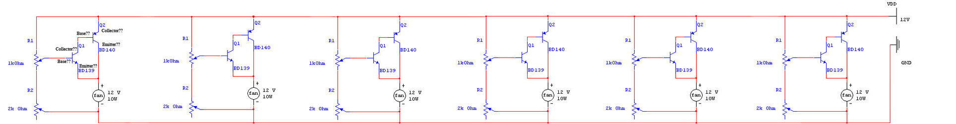
I want to be able to adjust the minimum settings for each fan. I read through a bunch of things on circuits but I don't think I'm getting it very well. So I thought I would show an image I altered, of a circuit posted by Venom. I hope the image turns out and every one kind of gets what I'm going after.
1. Would this set up allow each fan to receive enough power?
2. Are Transistors Q1 and Q2 labelled correctly (Collector, Base Emitter) in the left most portion of the diagram?
3. It says that it is for 10W fans, does it matter that my fans only add up to 10W if you add them all together? Well 9.96W.
4. And the 12V line and the ground go out to a molex connector right? What confuses me is the "VDD".
Ok so hopefully you smarties can help me. I just want to see if I'm even close to figuring this stuff out yet.
Delta AFB1212LE 12V .19Amp 2.28W
Delta ASB0812HH 12V .20Amp 2.40W
Delta ASB0812HH 12V .20Amp 2.40W
Vantec SF12025L 12V .08Amp 0.96W
Vantec SF12025L 12V .08Amp 0.96W
Vantec SF12025L 12V .08Amp 0.96W
I want to be able to adjust the minimum settings for each fan. I read through a bunch of things on circuits but I don't think I'm getting it very well. So I thought I would show an image I altered, of a circuit posted by Venom. I hope the image turns out and every one kind of gets what I'm going after.
1. Would this set up allow each fan to receive enough power?
2. Are Transistors Q1 and Q2 labelled correctly (Collector, Base Emitter) in the left most portion of the diagram?
3. It says that it is for 10W fans, does it matter that my fans only add up to 10W if you add them all together? Well 9.96W.
4. And the 12V line and the ground go out to a molex connector right? What confuses me is the "VDD".
Ok so hopefully you smarties can help me. I just want to see if I'm even close to figuring this stuff out yet.