- Joined
- Jul 5, 2003
- Location
- Frederick, MD
In my science research class, my group is building a flood & drain hydroponics system. We got everything working except for a timer to control the pump. Specifically, we needed to turn the pump on for 3 minutes every 45 minutes to an hour. Sadly, a lamp timer is not precise enough and no other interval timers that were made available to use met our needs, so the task of creating a working timer was handed to me. Originally, I had two ideas:
a) remove the second & hour hands from a large analog clock, glue a small magnet on the minute hand, then add magnet reed switches at the times we wanted the pump to turn on and off. The pump switched on & off using a relay, and a simple logic circuit would be built to handle the input from the reed switches.
b) modify one of the existing electro-mechanical lamp timers to run faster & therefore more precisely. I tried this and while I successfully changed the timer's intervals from 1 hour to 2 minutes (30x faster), I also succeeded in reducing the available torque to such a point the timer no longer had enough power to turn the switch. Obviously, this was a failure.
After the timer failure, I decided on a third a idea, a relay controlled via a computer's parallel port. As with most of us, I had an older machine readily available for use in our project. Ironically, I didn't have an analog clock available, so this plan became the cheapest idea after plan b. My build process is documented below.
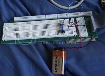
Since a parallel port is sensitive and unable to supply much current, a transistor is used as a buffer to switch a small reed relay. The circuit I used for this was shamelessly taken from here. If you're wondering, the circuit was prototyped on an awesome development board dating back to the days of Apple ][. My school was just going to throw it out, so I grabbed it

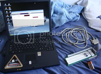
Here's a shot of my aging laptop + the protoboard. Originally, I was going to write my own control program in BASIC, but it turns out a program called Relais Timer already does what I needed.

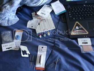
After I determined that the project was indeed feasible, I drove out to my friendly neighborhood Radio Shack and bought the components. Included is a 12v relay, 5v reed relay, D-sub connector, D-sub housing, various silicon diodes (1N400x), various resistors (1k + one that depends on your power source & relay), various NPN transistors, and a prototype board. Not pictured are a 10:1 transformer ripped from a stereo, a diode bridge I found, and a random 25v 3300uF capacitor for the power supply section.

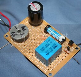
On the protoboard:

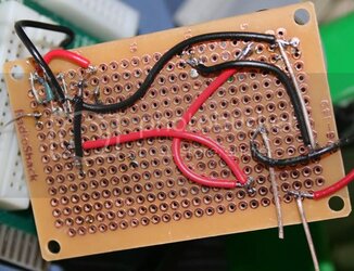
The back & being tested:

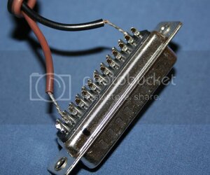
D-sub:

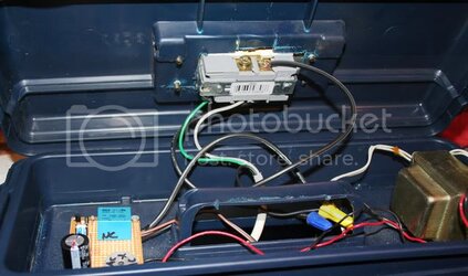
I wasn't willing to pay Radio Shack an insane amount of money for an enclosure, so I turned to Lowes instead. I found this lovely toolbox on clearance for $3.98. I also picked up an outlet and a faceplate. The faceplate is made out of a material that I don't recommend cutting with a dremel. My eyes & nose were burning from the dust...

Inside the toolbox, you can see the transformer, outlet, and circuit I built. It's very simple.

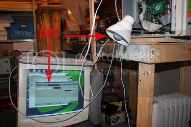
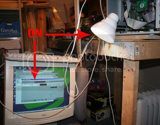
Here is the donor computer with a test lamp clamped to it. Don't worry, I'll put the case back together before it it is brought to school.

a) remove the second & hour hands from a large analog clock, glue a small magnet on the minute hand, then add magnet reed switches at the times we wanted the pump to turn on and off. The pump switched on & off using a relay, and a simple logic circuit would be built to handle the input from the reed switches.
b) modify one of the existing electro-mechanical lamp timers to run faster & therefore more precisely. I tried this and while I successfully changed the timer's intervals from 1 hour to 2 minutes (30x faster), I also succeeded in reducing the available torque to such a point the timer no longer had enough power to turn the switch. Obviously, this was a failure.
After the timer failure, I decided on a third a idea, a relay controlled via a computer's parallel port. As with most of us, I had an older machine readily available for use in our project. Ironically, I didn't have an analog clock available, so this plan became the cheapest idea after plan b. My build process is documented below.
Since a parallel port is sensitive and unable to supply much current, a transistor is used as a buffer to switch a small reed relay. The circuit I used for this was shamelessly taken from here. If you're wondering, the circuit was prototyped on an awesome development board dating back to the days of Apple ][. My school was just going to throw it out, so I grabbed it
Here's a shot of my aging laptop + the protoboard. Originally, I was going to write my own control program in BASIC, but it turns out a program called Relais Timer already does what I needed.
After I determined that the project was indeed feasible, I drove out to my friendly neighborhood Radio Shack and bought the components. Included is a 12v relay, 5v reed relay, D-sub connector, D-sub housing, various silicon diodes (1N400x), various resistors (1k + one that depends on your power source & relay), various NPN transistors, and a prototype board. Not pictured are a 10:1 transformer ripped from a stereo, a diode bridge I found, and a random 25v 3300uF capacitor for the power supply section.
On the protoboard:
The back & being tested:
D-sub:
I wasn't willing to pay Radio Shack an insane amount of money for an enclosure, so I turned to Lowes instead. I found this lovely toolbox on clearance for $3.98. I also picked up an outlet and a faceplate. The faceplate is made out of a material that I don't recommend cutting with a dremel. My eyes & nose were burning from the dust...

Inside the toolbox, you can see the transformer, outlet, and circuit I built. It's very simple.
Here is the donor computer with a test lamp clamped to it. Don't worry, I'll put the case back together before it it is brought to school.
