• Welcome to Overclockers Forums! Join us to reply in threads, receive reduced ads, and to customize your site experience!

Home made fan controller

Overclockers is supported by our readers. When you click a link to make a purchase, we may earn a commission. Learn More.

deadlysyn

Folding Team Content Editor, Who Dolk'd my stars S
Joined
Mar 31, 2005
Location
Stealing your megahurtz at night
So I am looking for a way to make a fan controller that would automatically adjust fan speeds depending on temperatures. I had this idea the other day, because I am working on putting together a water cooling loop, and I don't really trust Speedfan to do it, and would rather just build something. I was looking at the guide above to make my own PWM fan controller, and thought to myself, instead of the Rheo, why not find a way to have it adjust automatically. If there is a way that I can solder some parts in that would allow me to set a temperature where the fan speed changes, even if by jumpers or changing out a resistor, diode, or whatever it might be, I would love to hear it. Chances are for the temp sensor, I will be using THIS. This will be controlling 3 120mm fans, which i would prefer to each have their own circuit. If there was a way that I could have it pass data on to the computer as well, that would be something interesting to add, but I don't know the first thing about writing any programs.
 
Thermistors will change in resistance based on the temp. You could use one of those (plus possibly some other circuitry) to change the output of the PWM.
 
There is more to it then just a thermistor, that would only turn the fan on and off depending on what your using. They will not control the fans speed though. They use resistance to ground and that value is then given to a module with a set parameter which controls the amount of voltage to the fan.

Using a Thermistor you would have as an example: Temperature = 50 degrees, Resistance value 35 Mega Ohms. Tempure = 100 degrees Resistance = 500 Ohms and so on. So it would be a variable resistor, but the amount of current you could send through it would be limited. I am speaking from an Automotive Application where such a resistor may be 12V but more likely 5V. When you try and pull 40Amps through that circuit you will in all likely hood kill that Thermistor. Additionally the one I am referring to is an Automotive Temperature Sensor, I can't imagine a smaller one being able to do what you want without it using a control module.

What you need is two circuits, where the Thermistor is the control circuit with maybe a 2 or 3V reference signal to a control module to turn on your fans. Where would you install this anyways? under the HSF? or just ambient case temp?

I would think it would be easier to just use the CPU Fan output as the control to a fan controller. Set the fan controller or Pumps or whatever on high and done.

The way this would be set up would be a temperature sensor in the water loop, which will be hooked up to the controller and would hopefully be controlling fan speeds based on the temp of the water in the loop. I want to set it up so that, for instance, if the water was 60C, that it ramps the fans up to 100%, but if the temp is lower than the preset, to run at about 58% (about the equivalent of 7 volts) of the rated speed via PWM (which pulses 12 volts to the fan instead of lowering voltage). The reason I want to do PWM, is due to the fact that they lose torque at lower voltages, which decreases airflow, but running 12 volts in short bursts to get the fan speed you want will keep the torque and airflow, with less noise. This information is based off the fan mods sticky up above.
 
Hrm, well being that you are talking about a W/C loop. It is very similar to a Car. They sell Thermistors (Coolant Temperature Sensors) that are designed operate under variable resistance. When you input 5V or 12V to them, they return that voltage to the Control module, which in turn turns on the fan. You could probably use the same sensor. Normally on a car, the differences in temp. determine the injection Pulse Width of the injectors so they get more fuel when the car is colder. In your case the Pulse width could be used for the fans. The trick is the circuitry inside the control module, thats where it gets complicated. You could however build a set of transistors that open at different Voltage thresholds. So that as the temperature increases, the resistance decreases and the voltage increases. As a matter of fact, if your only running 5-12V to your Fans, a temperature sensor "might" withstand the amperage. Dunno, I have never tried something like that. If it does, then Your fan speed would vary depending on the resistance in the sensor. On the low side, it wouldn't matter because most 80-120mm fans have a low voltage threshold, so more or less it would just cut off. But on the high end, if your PSU is only putting out 12V then that should be the high. Just a thought. If that worked, you could tap a hold in your resevoir and just use the temp sensor, only problem would be you might need one for each fan depending on the load it can hold. Most temp sensors for cars are not expensive, so I would give it a go. As a matter of fact, I have a couple at work. I might just try and do some tests.

On a side note: This will probably work in a practical sense, but if it does, for the temps your talking about on a WC setup You would need a lot finer Thermistor. On a car the temps vary between (actually below freezing) 20 degrees up to 250 F degrees or higher.

Another way might be to just get... say 3 or 4 different thermistors, each designed to operate at a different temperature (on/off switches if you will.)
You could then switch each to a transistor on say a 2 or 3V circuit to the base of the transistor. Then have each of the 4 transistors running different voltages to the Collector and then run the emitter through a surge capacitor? on to the fans. I would imagine a capacitor could handle a single fan. If not, then only use 3v on each of the collectors, but run each of the emitters to a relay and then have each relay leg using 6, 8, 10, 12V. this would give you the option of variable speed, but not with PWM.
 
Last edited:
I think I may need to clarify what I am actually wanting to do here. For starters, here is the guide to the fan controller:
http://www.overclockers.com/forums/showpost.php?p=4253267&postcount=2
Here is a link to the thermal sensor I am looking at:
http://www.jab-tech.com/Bitspower-S...re-Sensor-Stop-Fitting-BP-WTP-CT-pr-4345.html

I was hoping there was a way that I could build a circuit that replaces the rheostat on that controller, which would send a signal that adjusts the fan speed based on the temperature from that particular sensor. I hope this makes a little more sense.:beer:
 
temperature-controlled-fan-12v-dc.GIF


Although I think in the end you might just be doing a whole lot of work for nothing.

You can buy a PWM fan pretty inexpensive. Then just attach a variable resistor/thermistor in place of the rheostat. It really is the cheapest/fastest/most efficient way.
 
Last edited:
For Example, this fan.

And this

Or use that thermistor and where you put a rheostat on Skieth's Controller, wire in that Thermistor instead. Run it to your radiator, (resevoir would work, but since its your radiator your cooling, you should epoxy it there or just before there in a coolant line.

P.S. The Rheostat is the 10K Ohm Potentiometer. I also missed the This Sensor in your original post. I don't know if that one would work. Essentially, Skeith designed that controller with a 10K Ohm Potentiometer. Basically it would allow you to probably dial in from 1000 (1K Ohm) - 10,000 (10K) Ohms.
So basically whatever sensor you use has to do the same with the Highest temp you want it to operate at the 1000 (1K Ohm) and the Lowest 10,000 (10K Ohm). You can test this by dropping it pot of water on the stove and slowly warming it up. The Higher resistance slows your fan down, the lower resistance is max speed.

I hope I helped. :/
 
Last edited:
temperature-controlled-fan-12v-dc.GIF


Although I think in the end you might just be doing a whole lot of work for nothing.

You can buy a PWM fan pretty inexpensive. Then just attach a variable resistor/thermistor in place of the rheostat. It really is the cheapest/fastest/most efficient way.

This will be set up on my radiator, which will be controlling 3 fans. I thought about doing one that just adjusted voltage based on temperatures, but I have read that PWM is better for the longevity of the fans. Also, according to my reading, running fans at less than their rated voltage decreases their torque, which in turn decreases pressure. When it comes to WC, the more pressure the better. Once I have a chance, I will take a look at the diagram posted, and see if it will do what I am looking for.
 
i am looking for a circuit with the same requirements as well.

looking at the diagram u posted with pwm output, can't you just wire the sensor(or thermistor)
between the +12V and the rheostat?

i am currently making the pcb for that schematic but i don't have a sensor to try it with.
 
What you say is true regarding PWM, thats why I went back and looked at the Controller Skieth drew up. It will do what you want. You just need to swap out the actualy rheostat with a 10K Ohm Thermistor.
 
So I am looking for a way to make a fan controller that would automatically adjust fan speeds depending on temperatures. I had this idea the other day, because I am working on putting together a water cooling loop, and I don't really trust Speedfan to do it, and would rather just build something. I was looking at the guide above to make my own PWM fan controller, and thought to myself, instead of the Rheo, why not find a way to have it adjust automatically. If there is a way that I can solder some parts in that would allow me to set a temperature where the fan speed changes, even if by jumpers or changing out a resistor, diode, or whatever it might be, I would love to hear it. Chances are for the temp sensor, I will be using THIS. This will be controlling 3 120mm fans, which i would prefer to each have their own circuit. If there was a way that I could have it pass data on to the computer as well, that would be something interesting to add, but I don't know the first thing about writing any programs.

I used a pulse width modulation fan and spliced into a 4-pin header with some longer wire and hooked it up the Main board's pin-out for the CPU and it works like a charm!


My 120mm PWM fan is in a push configuration with a BIX 120mm radiator. I could let the mainboard do the work for the PWD settings but I chose to use the gigabyte MB software and have set temperature ranges with corresponding fan speeds. i.e. set fan to minimum of 50% then start to ramp fan speed from 25C to 100% at 40C. It works quite well and does not require any external controlers or temperature sensors.

The mainboard pinout will carry 1amp for most boards which is more than enough for 1 fan. If you need to run a lot of fans or very powerful fans connect the power line to a regular positive rail from a spare molex and the ground. The PWM and sensor lines need to stay though.

Let me know if you need more help, and ill try to post pics when I get home.

Edit: http://www.overclockers.com/forums/showthread.php?t=612078 I brought this subject up a long time ago
 
Last edited:
I used a pulse width modulation fan and spliced into a 4-pin header with some longer wire and hooked it up the Main board's pin-out for the CPU and it works like a charm!


My 120mm PWM fan is in a push configuration with a BIX 120mm radiator. I could let the mainboard do the work for the PWD settings but I chose to use the gigabyte MB software and have set temperature ranges with corresponding fan speeds. i.e. set fan to minimum of 50% then start to ramp fan speed from 25C to 100% at 40C. It works quite well and does not require any external controlers or temperature sensors.

The mainboard pinout will carry 1amp for most boards which is more than enough for 1 fan. If you need to run a lot of fans or very powerful fans connect the power line to a regular positive rail from a spare molex and the ground. The PWM and sensor lines need to stay though.

Let me know if you need more help, and ill try to post pics when I get home.

Edit: http://www.overclockers.com/forums/showthread.php?t=612078 I brought this subject up a long time ago

I will be running a triple rad, which has 3 fans, and the fans I have are only 3 pin (12v+, GND, and RPM). The probe thermistor that was previously linked will not work in this situation, since it is too long for the res, and can not be installed into the rad without destroying it. I am simply looking for a circuit that will replace the rheostat mentioned in skeith's guide. Instead of being variable, like a rheo, I want something that would run the fans at 100% if temp is higher than a preset temp, and at 60% if lower than the preset temp. Basically I want the whole thing automated, so that I don't have to interact with it, unless the controller fails.
 
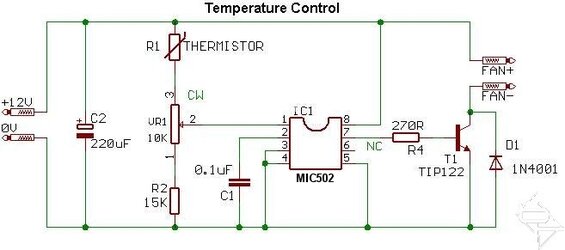
So after doing some looking around, I was able to find this:
2.jpg
It looks like it is virtually the same thing as BF has been trying to explain. So at this point, how would I go about setting the temperature that I want the fans to ramp up at. If I wanted them to go full speed at 50°C, would it be a change in a resistor somewhere, or do I need a specific thermistor?
 
Either actually. Finding the right resistor might be difficult though, since we are talking about temperatures where your fans should come on at say... 60, ramp up to 90 full blast but shut off after 50. But choosing the right thermistor would get you closer. More or less you could just trial and error. Find a Temp. sensor that is 10Kohms at ambient, and warm it up by about 30 degrees, it shouldn't drop to under 1K ohm.
 
I had shot out a PM to someone earlier today about this, since they are posting in threads like this one quite regularly. A couple of points were brought up, which I will address here as well. One of them, is that I could be spending hours at a time on trial and error, trying to get the temperature to fan speed at the balance I want. Another being that some fans have a tendency to make some noise when controlled via PWM. There is also the idea that fans don't lose any power or torque when they are undervolted, but will work exactly the same whether controlled via PWM or voltage adjustments. I was also thinking about leaving an option to add a display to monitor fan speeds, which can not be monitored if the fan controlled with this type of controller. Because of these things that I have not thought of previously, I am reconsidering this controller build, and thinking about doing a linear type of controller, which may still allow the monitoring of fan speeds.
 
Well, I was going to say, undervolting only loses the amount of torque your undervolting, but just because you PWM does not mean it will give you more torque.

As far as trial and error goes, thats only if you don't know the exact numbers/components your dealing with. Your going to fabricate with what you have... that way you save money.

One way to "fine tune" is to just install a 1k or 10k rheostat inline with your thermistor.

On the note of thermistors. I have a 20 degree thermistor at work you can have I tested it from 1K Ohm (Ambient 20 degrees) - 10 Ohms (60 degrees Celcius). You can build your module based off of that. If I come across a 10K Ohm thermistor, I will let you know. This thing has like a 7/8ths thread on it. and would have to be screwed in about 1". I could probably modify something though you could put inline of the radiator with 1/2" fittings.
 
2010-01-06%2000.58.47.jpg


2010-01-06%2000.59.08.jpg


Sorry, typo, not 20 degrees, 120 degrees. This should handle a 12V current @30A so you could run directly through it.

And those are 1/2" Compression Fittings.

Sorry about the crappy cellphone pics. I am at work.
 
Sorry, typo, not 20 degrees, 120 degrees. This should handle a 12V current @30A so you could run directly through it.

And those are 1/2" Compression Fittings.

Sorry about the crappy cellphone pics. I am at work.

That actually looks like it may be something that would do the trick, although I don't know much when it comes to making my own electronics. Are those compression fittings suited to 1/2" ID 3/4" OD tubing? I am also wondering how much restriction this would introduce into my loop. That is the primary reason I was looking for something small, that I could fit into my res. Once the temps equalize in the loop, it wouldn't matter where the thermistor is, since the temps will be the same at any 2 points in the loop. Atleast that is what I gather from my reading in quite a few guides and in the water cooling section.

Feel free to shoot me a PM regarding that thermistor when you have a chance.

Edit: How would the guage of wire soldered to the terminals affect the resistance? I have some wires about maybe 20GA that I was thinking about running for this, since it is small, and very easy to work with, for wire management. The fans I will be using are just medium speed Yates, I think at around 0.4A each.
 
Last edited:
Back