- Joined
- Jul 18, 2010
- Location
- Spokane, WA
Hello,
I hope this is in the right place, but I've just gone down to Radio Shack and grabbed all the components to throw together LennyRhys' PWM controller from his guide here http://www.overclockers.com/pwm-fan-controller
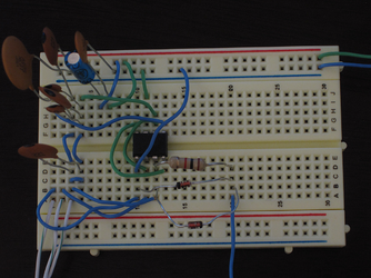
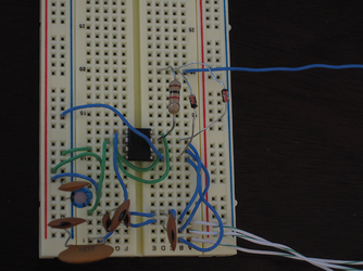
Anyway, I'm not that great at reading electrical diagrams but thought I did well enough and what I have on my breadboard seems to match after quadruple checking everything. I must be a n00b though 'cause it's not working
Are the C2's laid out wrong for a series layout?
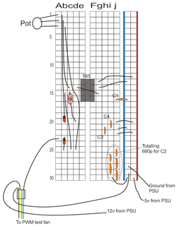
Here is my layman's drawing to exactly how I have it laid out (since a pic of my actual board probably wouldn't work well):

I REALLY need to get this working to slow down my pump so my water-cooled system isn't as loud as my old air-cooled box which is replaced (and to increase pump life of course).
Can someone (BING??) take a look really quick at this and let me know what may be wrong?
When plugged in to the PSU, the test fan I have runs, but turning the POT doesn't do anything at all
Thanks a ton in advance and please don't laugh if something is blatantly obviously wrong, lol.
I hope this is in the right place, but I've just gone down to Radio Shack and grabbed all the components to throw together LennyRhys' PWM controller from his guide here http://www.overclockers.com/pwm-fan-controller
Anyway, I'm not that great at reading electrical diagrams but thought I did well enough and what I have on my breadboard seems to match after quadruple checking everything. I must be a n00b though 'cause it's not working

Are the C2's laid out wrong for a series layout?
Here is my layman's drawing to exactly how I have it laid out (since a pic of my actual board probably wouldn't work well):

I REALLY need to get this working to slow down my pump so my water-cooled system isn't as loud as my old air-cooled box which is replaced (and to increase pump life of course).
Can someone (BING??) take a look really quick at this and let me know what may be wrong?
When plugged in to the PSU, the test fan I have runs, but turning the POT doesn't do anything at all
Thanks a ton in advance and please don't laugh if something is blatantly obviously wrong, lol.

