• Welcome to Overclockers Forums! Join us to reply in threads, receive reduced ads, and to customize your site experience!

Investigation into PSU noise. Corsair CX600.

Overclockers is supported by our readers. When you click a link to make a purchase, we may earn a commission. Learn More.

cyberfish

Member
Joined
May 23, 2008
Location
London, England
This is a continuation of the (derailed) discussion in this thread: http://www.overclockers.com/forums/showthread.php?t=711607

So the story is, I have a Corsair CX600 that powered my computer fine until I put in a new video card (from 560 Ti SLI to single 670). It can't be power draw because 2x560 Ti draw way more than a 670 (neither were overclocked).

However, with the 670, whenever the card is doing something, my computer would get all sorts of noise - audible noise of different frequencies from speakers, "wavy" lines on my VGA LCD, and even artifacts in ATI Tools.

My guess is the new video card's vreg PWMs at a frequency that the CX600's regulation loop is unstable at, and cause rail oscillation. I have not found proof for this.

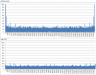
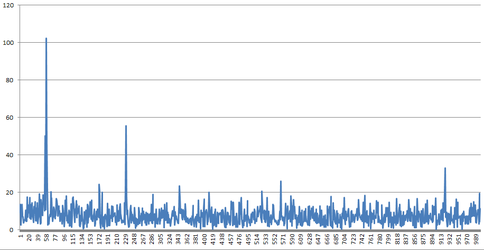
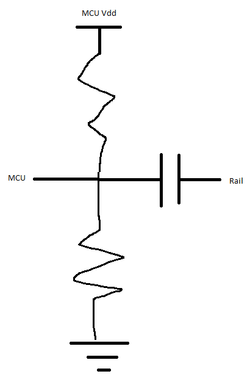
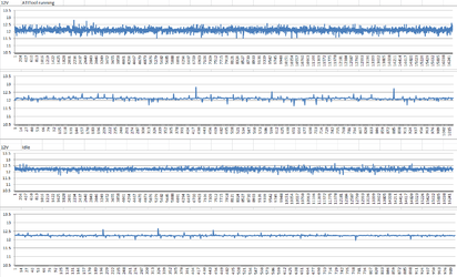
Since I don't have an oscilloscope with me right now, I built a little circuit using a STM32 board I had lying around to plot the rails with the 670 running and without.

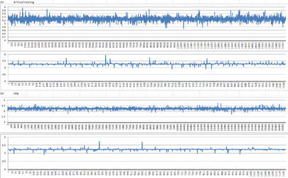
Unfortunately I didn't see any noticeable difference except bigger ripple. The rail regulation does look pretty bad, but I don't see any significant frequency component in the audible range. It could also be due to my ghetto setup (input capacitance, BW, etc), so I will hold off on blaming Corsair until I get a chance to test it on an oscilloscope (in about 2 weeks).

In the mean time, attached is what I saw. X axis is sample number. Sampling rate is 100kHz. In each group, the first graph is all samples (16000 samples), and second graph is zoomed in picture to where it looks like it's the worst.

The sampling circuit is powered by USB from a laptop running on battery (to make sure rail oscillation won't affect the measurement circuit).

I will be very disappointed if these measurements turn out to be valid. Yes, CX600 is their low end series, but it also bears the Corsair name, and this is definitely not what I would expect Corsair quality to be.
 

Attachments

  • 5V.png
    5V.png
    33.1 KB · Views: 1,113
  • 12V.png
    12V.png
    29.6 KB · Views: 1,069
If that thing is accurate, that PSU is woefully over ripple spec and regulation spec.
 
is it fair to measure voltages via software? arent they usually pretty unreliable?
 
Via software, not reliable.
Via external microcontroller, somewhat.
The MCU's I've seen can get confused at a high sample rate, I don't know about that one.
 
what is an mcu? i havent learned anything from all of your reviews i suppose lol :D stuff just dont sink in for me
 
Sampling circuit is this guy - http://www.st.com/internet/evalboard/product/252419.jsp

With a simple resistive divider.

It's capable of sampling at 2.4Msps, so 100Ksps should be very easy.

I didn't check the input impedance into the MCU, but the only effect it would have is shifting the DC level a little bit, not the ripple. The input capacitance would decrease the bandwidth and make ripple appear smaller not bigger.

It's theoretically possible that the sample and hold circuit coupled with inductance of the wires cause some additional ripple, but I have never seen it in real life, and I highly doubt that's the case.

I'm very surprised how bad it looks either, but will have to check it with a scope to make sure.
 
I think I will try RMA first, since I won't have access to a scope until I go back to Canada, and shipping power supply from Canada would cost a lot more.

If the new PSU is fine I guess all is good and this unit is just defective. If not, I'll do more investigation with the replacement.
 
I've seen ripple that bad (today's frontpage PSU review for instance) but I'd be pretty surprised if a Corsair did it. That said, every manufacturing process has issues sometimes.

Nvidia won't let you bring it in and use a scope at work on your lunch break or something?

EDIT:
Can you try at say, 1Msps? It'd run out of ram sooner of course, but it might show some curve to the ripple if there is any.
 
They wouldn't mind, but I would have to haul my whole computer over...

I could try 1Msps, but that requires a lot more coding (I'm using software single triggering right now, and 1Msps would require setting up DMA, and I have never done that on this chip).
 
Benching has led me to haul my computer and various bits around so much I forget that most people don't. I live in my own little world really :p

Is 100Khz as fast as it'll go in software?
 
Yeah 100KHz is the fastest I can make it go.

100KHz should be able to detect anything up to 50KHz ripple already, though, and I think what I'm looking for is in the audible range (<20KHz). Maybe I'll try running FFT on the data and see what the frequency spectrum looks like.
 
I wonder if Corsair would send me one for review, I'll have to check.

There are some regular bumps in the top chart, what is the time scale on it?
It looks like some of it is the poor reaction of ADCs with transient voltage spikes, even some digital scopes seriously dislike them and read them dubiously.
I tested my scope and a modern digital scope back to back and found that the transients were read very differently.
On digital scopes of all sorts it is difficult to see exactly what is up sometimes.
As an example:
TtS1000M-12V-HOTCL12Vw-50mV-10us.jpg
This type of shot digital scopes typically show a spike further upward and downward or hack the little transient spikes off entirely, depending on their settings. Playing with the settings you can take the transients away entirely or make them display at any level you want. It's really rather odd.
(That's at 10 microseconds per divider, it's switching at around 84kHz. 50 mV per divider)
That one didn't make noise, however then the APFC bits went into oscillations and gave me this(same 12v rail):
TtS1000M-12V-HotFail192w12v-50w5v-22w3.3v-scope-at-100mv-0.2ms.jpg
That's 200 microseconds/divider (and 100 mV). You can still see the 83kHz switching waveform on the slower ~2kHz regulator oscillation waveform. On a digital scope you'll just see a single thick trace, or a thick trace with occasional spikes on it.
That unit got a FAIL stamp, for fairly obvious reasons :p

Anyway, I'm curious about the time scale on your most recent load picture because it looks like there might be something similar to my second example shot going on.
 
Last edited:
The frequency scale, IIRC, is sampling rate / # samples, so that would be about 6.25Hz.

Attached is zoom in of 0-1000 (0 - 6.25KHz).
 

Attachments

  • fft.png
    fft.png
    29.7 KB · Views: 1,029
Oh and sorry these are in frequency domain, not time domain. They are generated using FFT because I don't have a spectrum analyzer.
 
Ahh I wasn't thinking FFT, that makes things make a little more sense.

How many raw samples can that unit store (alternatively, how fast can it dump raw data to the PC?)? If it can do 100kHz for a few ms you could use it to make a rough oscilloscope.
Even a 2ms slice of the raw data turned into a graph could give you an idea of the switching waveform.
The units I use have, at most, a whopping 2k of ram, enough to store maybe 1.5ms or so at 100kHz of 8bit readings and still leave enough to spare to run the program.
They cannot, however, reliably sample anywhere near that fast.


Argh, now you've got me thinking about how to get AC mode data out of it like a scope.
It might just blow the MCU to hell, but if you're using an independent battery supply (which you are, more or less) you should be able to do something creative like make the divider much lower or ignore it completely and then make a second divider to take the 12v(ish) and drop it to 10v, then put a fairly juicy cap or three on it. Use that 10v as the "ground" for the reading then the 12 V rail will appear as 2v and the MCU can read the voltage directly, giving it far finer measurements than with the 12v dropped to TTL levels with a divider.

I've played with this sort of thing with my scope and isolated battery supplies with good success, given that the laptop/battery is isolated it really doesn't care overly much what the "ground" is connected to in theory.
I'd hate to blow your laptop AND MCU to hell though, so personally I'd work up a battery supply for the MCU that doesn't involve a laptop, and switch to a cheaper MCU if that one is pricey.
I generally work with $1-$4.50 MCUs, partly for that reason.
 
It's strange that you see different transients on analog vs digital scope. I don't have much experience with analog scopes (maybe a few hours total), but they all seem to agree.

Maybe the transients are so short that the analog scope cannot pick it up? I have never seen digital scopes inserting transients that aren't there in reality. You can make them go away probably with noise reject or bandwidth cap setting on the digital scope, but that just decreases the bandwidth of the scope.

How many raw samples can that unit store (alternatively, how fast can it dump raw data to the PC?)? If it can do 100kHz for a few ms you could use it to make a rough oscilloscope.
The original graphs on the first post have 16000 samples, so that's 160ms total. They are 12-bit samples. 128KB RAM (I'm storing the data inefficiently). I also talk to it over full speed USB, so at 100kHz I can even just stream the data to PC.

Argh, now you've got me thinking about how to get AC mode data out of it like a scope.
It might just blow the MCU to hell, but if you're using an independent battery supply (which you are, more or less) you should be able to do something creative like make the divider much lower or ignore it completely and then make a second divider to take the 12v(ish) and drop it to 10v, then put a fairly juicy cap or three on it. Use that 10v as the "ground" for the reading then the 12 V rail will appear as 2v and the MCU can read the voltage directly, giving it far finer measurements than with the 12v dropped to TTL levels with a divider.
The divider is only 5:1 (IIRC) for the 12V rail, and at 12-bit samples, that's still 3.6mV resolution. I don't think my setup is good enough to need more than that kind of resolution.

Though if I were to do it, I would AC couple the line through a capacitor, and bias it to, for example, 1.5V through a resistive divider between MCU Vcc and GND. I believe that's what scopes do, too (the capacitor is selected by a relay).
 

Attachments

  • bias.png
    bias.png
    8.9 KB · Views: 1,007
Back