The following How-To gives a blow-by-blow description of how I made a water-cooled peltier rig. This super-cooling setup enables me to run my C366 @ 566 MHz. I set the BX6 rev2 bios at 5.5 X 100 with turbo. I think the extreme cold alters the bus or multiplier. All programs recognize the chip at 566 or 567. As you will see, condensation at low temperatures is a key concern and the insulation I used is a major part of any super-cooling effort.
The Complete Parts List for a Water-Cooled Peltier
Peltiers: 2 Melcor PT8-12-40: $36.50
Peltier Power Supply: 11.5V to 14.5V DC 25A. The two peltiers need 17A max. I found this at an electronics surplus
store: $65.00
Liquid Cooled Heat Exchanger: Melcor LI-401-CL: $70.00
Thermal Grease: Melcor TG-003
Fountain Pump: Home Depot 125 GPH 110V AC: $20.00
Copper Line: 10′ – 3/8″. You’ll only need about a foot or two: $10.00
Soft Clear Tubing: 10′ – 3/8″ ID: $4.00
Brass Compression Fittings: 2 – 3/8″ to ¼” 90°. Depending on your board configuration you may need straight fittings instead: $5.00
Hose Clamps: 4 – 3-8″: $2.00
Fan: 6″ to 12″. I have a 12″ 110 V AC computer fan from an electronics surplus store. A small desk fan should work: $7.00
DAP Tex Spray Foam: You won’t have to use the whole can at once with this kind: $7.00
Pink Foam House Insulation: 1 1/2″or 2″ thick. I bought a sheet that is used to insulate bare basement walls: $9.00
Water Jug: I picked up an insulated half-gallon jug at a thrift store: $1.00
Cellophane & 3M Black Electricians Tape: I always have this stuff around: $?
Foam plate: that you get hamburger on. If you ask the butcher nicely he might give you a clean one free: $?
Aluminum bar stock: I bought a bunch of this when I started this project. I ended up using 3″x1/4″x6″ pieces for the cold & backing plate: $10.00
After-market Transmission Cooler: I got one from a “U Pull R Parts” yard – the ones with thin aluminum fins may work better: $6.00
Antifreeze: I had some in the garage: $?
JetDry: I added this – figured it couldn’t hurt: $?
The cold plates I used are probably much taller than they need to be – 2″x 1/4″x 6″ would probably work. My plates are 3″ tall because I bought the Aluminum stock that wide. I used ¼” thick because the Melcor site said that was the minimum thickness for Aluminum cold plates.
First, you need to drill the mounting holes in your two Aluminum plates. Center your chip and mark the holes. The
bottom two holes should be very close to the bottom edge of the cold plate. You have to counter sink these holes on the cold plate, water-cooled heat sink side. Then, use your water-cooled heat sink to mark the mounting holes on the cold plate. I drilled all four holes and ended up with the middle two on the edge of the Celeron heat slug. This is not ideal. You may be able to just use the outside two holes and still be OK. I counter sunk the holes for the water-cooled
heat sink bolts into the chip side of the cold plate.
Next, carve some foam with a coping saw to squeeze between the cold plate and the chip. The goal is to seal the edge, not to fill the entire area. Carve some more to fit around the slot one as best you can without covering up the BX heat ink. Keep this foam level with the top of the slot one. Cover the edges of the slot one and the foam with cellophane tape. Spray foam comes off cellophane tape easier than it comes off the Mother Board. Carve five more pieces of foam as
thick as space will allow to cover all the sides of the assembly except the connector. I used the spray foam as mortar between the foam pieces and cellophane tape to hold the pieces together. It doesn’t stretch and serves as an air barrier. After running the system for a while I noticed that the bottom of the motherboard gets cold. I taped over the motherboard under the slot one and sprayed it with the foam insulation for extra insurance.
Use Thermal Grease on the heat slug. Use four more counter sunk stainless steel screws, nylon washers, stainless washers, lock-washers, and then the nut to clamp the chip between the two Aluminum plates.
Next, carve some foam with a coping saw to squeeze between the cold plate and the chip. Carve some more to fit around the slot one as best you can without covering up the BX heat sink. Cover the edges of the slot one and the foam with cellophane tape. Spray foam comes off cellophane tape easier than it comes off the Mother Board. Carve five more pieces of foam as thick as space will allow to cover all the sides of the assembly except the connector. I used the spray foam as mortar between the foam pieces and cellophane tape to hold the pieces together. It doesn’t stretch and serves as an air barrier.
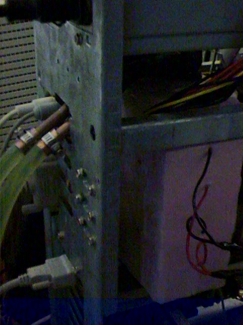
During the fitting of the foam, you should also decide where you are going to have the tubes exit the case. Once you have all the foam on, you can attach the 90° fittings and the copper tubes. It takes some wiggling to get everything to line up and pop in. You have to remove the PII or Celeron chip mounts for this to fit. Once fitted, you can spray a little foam around the slot 1 connector to seal the base foam to the chip foam. Be very careful to not get the foam too close to the slot. (Insert joke here) I have a cross brace in my case. I wedged a small piece of foam to hold the assembly in place, though I could have used wire to tie it down.
The rest of the connections are easy to figure out. I’m running my peltiers in parallel. The soft line easily connects to the pump and lines. The fittings on my transmission cooler are a little small, but I couldn’t get them out. I just tightened the clamps down as snug as I could.
The Case
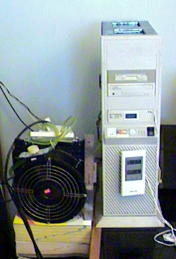
My case is an old full tower AT case I modified as an ATX. I did a lot of cutting on the back with a Dremel, cutting out spaces for the peltier power supply, the ATX power supply, the ATX back plate, and holes for the cooling tubes. This is the first system in three years that I’ve run with the cover on. It replaced a K6-166 that ran at 233 with a large heatsink and 3″ AC fan. The first system I over-clocked was a 486SX 25 to 33.

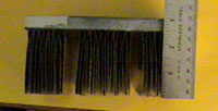
The Heatsink

I got the idea to do this from the little folded fin heat sink I saw on a PII 350. I used Aluminum roofing flashing to make the fins. I attached them to the base with Aluminum brazing rod using my gas stove. You have to be careful to not let it get to hot – it will actually eat the surface of the base. It takes a long time to grind off mistakes so don’t use too much as it will flow off the top and drip from the bottom. Also don’t burn your self – I take no responsibility for your injuries.

The Homemade Water Cooled Heatsink
This is three plates of ¼” Al. One has two ¾” tubes Alumaloyed to it. I used JB weld to attach the end plate, fittings, and to make sure that all of the seams don’t leak. I made this one to fit between the standard mounting brackets. One peltier powered from an extra AT power supply should be enough to cool a chip to the next level.

Be the first to comment