- Joined
- Jul 5, 2003
- Location
- Frederick, MD
I suppose this belongs here. I've been trying to digitize my families historic media which consist of 35mm kodachrome slides and 8mm film. I'm currently scanning the slides on a Epson V330 flatbed, but will probably buy a proper film scanner in the future. The 8mm isn't so straight forward.
There are different methods to digitize 8mm film. I believe most people project the video on a screen as normal, then record the screen. This method leaves a lot of quality on the table. Another option is to scan the film on a flatbed (in strips), then extract individual frames using special software and eventually stitch them back together. The flatbed method works well, but is slow, manual, and it's hard to hold every frame flat against the glass bed. The third method is to convert a projector to hold a camera and advance the film frame-by-frame, taking a picture each time. This is the method I am pursuing.
To start off, I acquired my grandfather's old 8mm projector, a Bell and Howell Regent Design 122 Model L. This is a rather nice standard 8 (silent) projector. I was initially concerned there would not be enough room to mount a camera between the film reels, but a later design revision made it a non-issue.

After making sure the projector itself was still in working condition - it is *always* a good idea to have a base line, I then started disassembling the projector to figure out how it works. For the telecine to work, I need to have control over the motor so that each frame can be advanced individually, rather than at at 18 frames-per-second.

^test 8mm film
I removed the entire motor & lamp assembly to find the shutter assembly. The shutter consists of three blades that spin. Each revolution of the shutter advances the film exactly one frame, and the shutter interrupts the light three times. This is because 18 fps is slow and we would see the film flashing - by flashing the same image three times in a row, it appears to be more persistent.

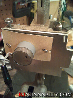
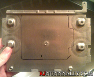
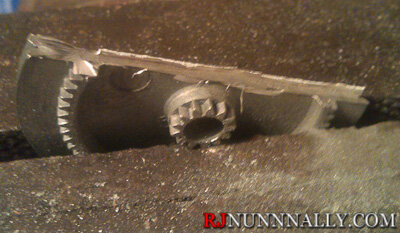
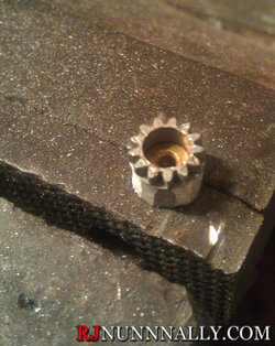
It turns out that this projector is a great telecine platform because of the way it is assembled and because the the shutter rotates once per frame. I removed the shutter "blade" and machined a gear from an old cassette deck to fit in place. I will fit a new plate to the back of the projector and drive the newly fitted gear with a DC motor, also from the cassette deck. Unfortunately, the motor is not a stepper motor so a closed circuit feedback system will need to be used to determine the position of the film.

I will be controlling the motor using a microcontroller, either a parallax propeller that I already own or an arduino. Neither is able to directly drive a "powerful" DC motor so I built a quick circuit to control the motor.

After it was bread boarded, I then worked on some crude PWM code to drive the motor at different power levels. It seems to work well enough, but it can certainly be optimized.

Above is a visualization of the PWM code running. Each square is 1 ms on the x axis.
That's where I'm at now. I still need to mount the motor, mount an LED light source, provide feedback to the microcontroller, and then mount a camera (probably a webcam) to take pictures when triggered by the microcontroller.
Read more here http://www.rjnunnally.com/tag/telecine/ . I'll provide updates as the project progresses, but I work full time & go to school full time so I'm not sure what the time schedule will be.
There are different methods to digitize 8mm film. I believe most people project the video on a screen as normal, then record the screen. This method leaves a lot of quality on the table. Another option is to scan the film on a flatbed (in strips), then extract individual frames using special software and eventually stitch them back together. The flatbed method works well, but is slow, manual, and it's hard to hold every frame flat against the glass bed. The third method is to convert a projector to hold a camera and advance the film frame-by-frame, taking a picture each time. This is the method I am pursuing.
To start off, I acquired my grandfather's old 8mm projector, a Bell and Howell Regent Design 122 Model L. This is a rather nice standard 8 (silent) projector. I was initially concerned there would not be enough room to mount a camera between the film reels, but a later design revision made it a non-issue.
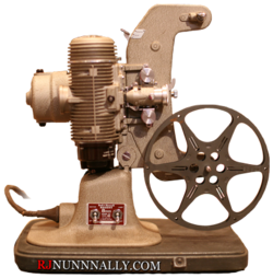
After making sure the projector itself was still in working condition - it is *always* a good idea to have a base line, I then started disassembling the projector to figure out how it works. For the telecine to work, I need to have control over the motor so that each frame can be advanced individually, rather than at at 18 frames-per-second.
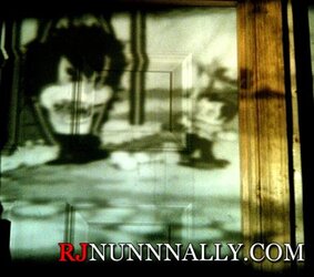
^test 8mm film
I removed the entire motor & lamp assembly to find the shutter assembly. The shutter consists of three blades that spin. Each revolution of the shutter advances the film exactly one frame, and the shutter interrupts the light three times. This is because 18 fps is slow and we would see the film flashing - by flashing the same image three times in a row, it appears to be more persistent.
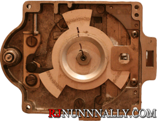
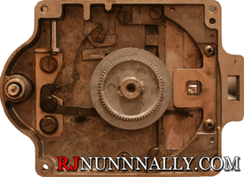
It turns out that this projector is a great telecine platform because of the way it is assembled and because the the shutter rotates once per frame. I removed the shutter "blade" and machined a gear from an old cassette deck to fit in place. I will fit a new plate to the back of the projector and drive the newly fitted gear with a DC motor, also from the cassette deck. Unfortunately, the motor is not a stepper motor so a closed circuit feedback system will need to be used to determine the position of the film.
I will be controlling the motor using a microcontroller, either a parallax propeller that I already own or an arduino. Neither is able to directly drive a "powerful" DC motor so I built a quick circuit to control the motor.
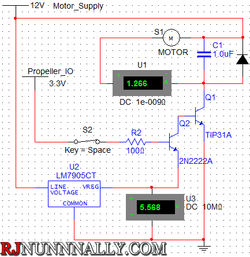
After it was bread boarded, I then worked on some crude PWM code to drive the motor at different power levels. It seems to work well enough, but it can certainly be optimized.
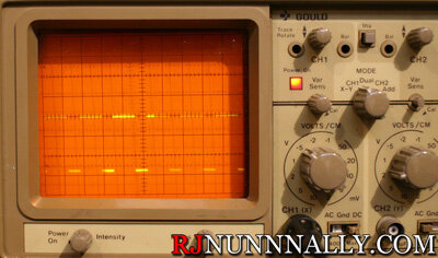
Above is a visualization of the PWM code running. Each square is 1 ms on the x axis.
That's where I'm at now. I still need to mount the motor, mount an LED light source, provide feedback to the microcontroller, and then mount a camera (probably a webcam) to take pictures when triggered by the microcontroller.
Read more here http://www.rjnunnally.com/tag/telecine/ . I'll provide updates as the project progresses, but I work full time & go to school full time so I'm not sure what the time schedule will be.
