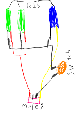
K I am wanting to wire some LEDs in my case to a rocker switch. Well problem is that some of my LEDs are 5v and some is 12v so how can I hook them up to a rocker switch? Or is it possible? I was thinking that on a molex you got 4 wires.. One red, one yellow and two blacks. Well yellow is 12v positive, red is 5v positive and the two blacks are ground..my theory is hook LEDs up way they should but there sharing ground basically so why couldn't I break circuit and put a rocker switch on ground side? Where all ground wires meet before going to PSU on that particular cable.
-
Welcome to Overclockers Forums! Join us to reply in threads, receive reduced ads, and to customize your site experience!
You are using an out of date browser. It may not display this or other websites correctly.
You should upgrade or use an alternative browser.
You should upgrade or use an alternative browser.
Need help with wiring a switch
- Thread starter Spyrotd
- Start date
- Thread Starter
- #8
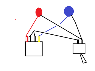
k for record.. red line is 5v + yellow is 12v + and the 2 blacks is ground and as you can see that 12 v and 5 v is hooked directally to molex the way they should be intended but only exception is that ground/black is wired all together before switch then lead directally to switch via 1 wire then to molex.. so the switch is breaking circuit via ground.. that is what I was thinking..
- Thread Starter
- #11
I don't think I need a dual input switch.. I just talked to someone that wired a motorcycle underglow leds up.. he told me that !s long as the 12v and the 5v is wired the way there intended to be.. the ground can be wired together and broken by a switch just like it shows in the picture so I am all set then..
- Joined
- Sep 13, 2015
You do not want to hook the switch into the ground as you have shown. As a general rule of thumb when working with electricity you want to break the hot/positive side of the circuit never the neutral/ground. If you hook it up the way you have drawn you will be creating a 7v circuit as blaylock mentioned. You would be better served by a DPST switch instead. This could also be accomplished by the use of a small relay if needed. I can see what I can do to locate the correct switch for your application, do you have any requirements for the switch such as size, colour or material.
- Joined
- Sep 13, 2015
Here is a quick link too an example of a DPST rocker switch.
http://www.amazon.com/gp/aw/d/B00OK...witch+dpst&dpPl=1&dpID=419G-fAk8cL&ref=plSrch
http://www.amazon.com/gp/aw/d/B00OK...witch+dpst&dpPl=1&dpID=419G-fAk8cL&ref=plSrch
Last edited:
- Thread Starter
- #15
lol I feel dumb.. I done some research and stumbled across this.. http://www.dummies.com/how-to/content/turning-electricity-on-and-off.html
what caught my eye was the definitions.. exspecially this one: Double-pole single-throw (DPST): This switch has two wires coming into it and two wires leaving. You can use a DPST switch to control two separate circuits. For example, you can have one circuit with components running on 5 volts and another circuit with components running on 12 volts. With one switch, you can turn both circuits on or off.
I went and looked at my switch and seen it has 4 poles k.. but I don't know if it is double throw or single throw.. cause I seen switches where one way is for 1 set of lights on and other set off and the other way is opposite where the one was on is now off and the other one is opposite also.. so I got my ohm meter and put it on ohm just to see as follows
so I flipped the switch one way and checked all four pins in every comination possible and got nothing so I see it isn't double throw.. so I flipped switch (I notice on this switch that the 4 pins is separated into 2 groups of 2 by piece of plastic) well I tried again and both pins on same side of plastic makes connection and the others are also same but wanted to see if this switch is also where the other pins on other side of plastic separater is not linked to others on other side so my results are I got a dpst switch! yay!! so just got to wire it up!!
below is my switch!!


and knowing this.. I can wire it up like this!

what caught my eye was the definitions.. exspecially this one: Double-pole single-throw (DPST): This switch has two wires coming into it and two wires leaving. You can use a DPST switch to control two separate circuits. For example, you can have one circuit with components running on 5 volts and another circuit with components running on 12 volts. With one switch, you can turn both circuits on or off.
I went and looked at my switch and seen it has 4 poles k.. but I don't know if it is double throw or single throw.. cause I seen switches where one way is for 1 set of lights on and other set off and the other way is opposite where the one was on is now off and the other one is opposite also.. so I got my ohm meter and put it on ohm just to see as follows
so I flipped the switch one way and checked all four pins in every comination possible and got nothing so I see it isn't double throw.. so I flipped switch (I notice on this switch that the 4 pins is separated into 2 groups of 2 by piece of plastic) well I tried again and both pins on same side of plastic makes connection and the others are also same but wanted to see if this switch is also where the other pins on other side of plastic separater is not linked to others on other side so my results are I got a dpst switch! yay!! so just got to wire it up!!
below is my switch!!
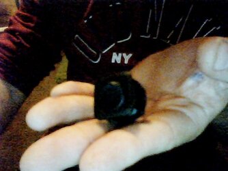
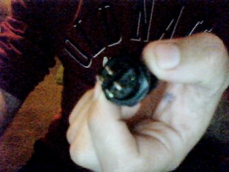
and knowing this.. I can wire it up like this!
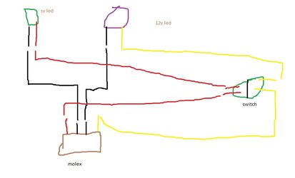
- Thread Starter
- #17
I want to be able to turn leds on and off.
I am adding few more lights.. so this is it "currently" but it is all torn appart cause doing some wire rerouting to screens and then this project.. upgrading gpu.. going liquid cool (in video it all air cooled. just need a pump, xspc razor gtx 780ti waterblock, a waterblock bridge for sli hence buying another 780ti verrrrrry soon. and lots and lots of fittings.. I got everything else.) and if I can finally get a hold of a good motherboard lol!! (asrock z97 ext3.. 1st my fault bent socket pins. 2 just wouldn't power up one morning.. 3 no sound due to fried sound processor.. 4 same as 3.. and finally got a good one! yes all them is rma! so basically everything is in pieces cause I am getting tired taking everything appart and putting back together hence going to be liquid cooling so might as well as wait till I get rest of my parts.
I am adding few more lights.. so this is it "currently" but it is all torn appart cause doing some wire rerouting to screens and then this project.. upgrading gpu.. going liquid cool (in video it all air cooled. just need a pump, xspc razor gtx 780ti waterblock, a waterblock bridge for sli hence buying another 780ti verrrrrry soon. and lots and lots of fittings.. I got everything else.) and if I can finally get a hold of a good motherboard lol!! (asrock z97 ext3.. 1st my fault bent socket pins. 2 just wouldn't power up one morning.. 3 no sound due to fried sound processor.. 4 same as 3.. and finally got a good one! yes all them is rma! so basically everything is in pieces cause I am getting tired taking everything appart and putting back together hence going to be liquid cooling so might as well as wait till I get rest of my parts.
You're breaking continuity. For the sake of a switch, it doesn;t matter if you turn off the + or the - side. The reason you break the + side is for safety (i.e. YOU becoming the ground is a bad idea lol). Since its in a case, and will essentially have a "master" power switch (the psu), as well as the main pc on off, it wont matter.
Heres a wiring diagram that will work just fine to turn both on or off. A double pole, double throw switch is not required.

Heres a wiring diagram that will work just fine to turn both on or off. A double pole, double throw switch is not required.
- Joined
- Sep 13, 2015
You're breaking continuity. For the sake of a switch, it doesn;t matter if you turn off the + or the - side. The reason you break the + side is for safety (i.e. YOU becoming the ground is a bad idea lol). Since its in a case, and will essentially have a "master" power switch (the psu), as well as the main pc on off, it wont matter.
Heres a wiring diagram that will work just fine to turn both on or off. A double pole, double throw switch is not required.
View attachment 171008
As I mentioned earlier I would not recommend wiring it this way because you will be creating a 7 volt circuit through the leds when the switch is off. You are correct that it is done for safety reasons and no reason to be unsafe just because it is in a case.
Similar threads
- Replies
- 3
- Views
- 2K
- Replies
- 2
- Views
- 416
- Replies
- 14
- Views
- 2K
- Replies
- 15
- Views
- 878
