• Welcome to Overclockers Forums! Join us to reply in threads, receive reduced ads, and to customize your site experience!

PROJECT LOG Project Unity

Overclockers is supported by our readers. When you click a link to make a purchase, we may earn a commission. Learn More.

WarWolf

Member
Joined
Aug 27, 2012
Location
Oregon
When I first built my current desktop way back in September, 2012 (geez, was it really that long ago?) I had it in a CM Storm Scout. It was my first build and I didn't really care for the size of it. Both for working in it and upgrade (liquid cooling mainly) limitations.

Summer of 2013 I got the urge to upgrade and ended up buying a CM Storm Trooper. Loved the look of the case, my graphic card no longer extended into the drive bays, dropped temperatures by 10c, and was much less of a hassle to manage cables.

Of course, the downside to a big case is that it has to go somewhere. Put it on the floor and either the cables were too short or airflow would be badly limited. So I was/am left with losing a chunk of desk space to the computer.

But not for much longer. Early June a friend sent me a link to a short article talking about a new "case" from Lian-Li that was a desk with mounting points for a motherboard and other hardware (rads, hard drives, etc). While I liked the design, the price tag was another thing. At ~$1000, I'm not picking it up anytime soon.

Couple days later I started thinking, and the more I thought about it, the more it seemed possible to make something similar myself. Thus, Project Unity (not completely set on the name, like it but may be subject to change) was born, uniting your desk and computer. So relax, sit back, and watch a first major mod/woodworking project unfold.

Index:
1. This post
2. Shining Light on the Situation
3. Pull the Third Lever
4. Who needs names?
5. Control Panel and Blinking Lights
6. Re-Mounted Control & Crazy Malwarebytes
7. PSU & Motherboard tray mounting
8. Who needs cables?


--The Plan--
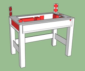
Front
Desk.jpg

No fancy renders here. Red parts are components.

10x120mm fans, 10 drive bays, up to XL-ATX, speakers, control panel (lights, fans, etc)

Possible features are phone dock and touchscreen.

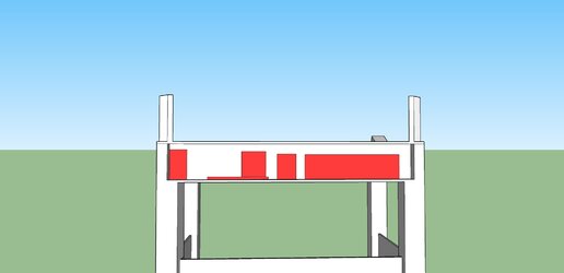
Back
Desk3.jpg

Left to right: PSU, motherboard, hard drive access, 360mm radiator.


Now, onto the actual building part.
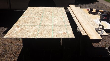
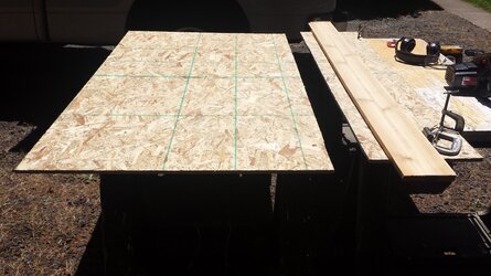
NOTE: The project currently is a prototype/proof of concept. Because of this and my inexperience, the desk will initially be built using OSB. It's cheap, so screw-ups aren't a huge hassle.

I don't currently the tools nor the experience to build it from metal, so it will have to be wood instead. Plus, I think a nice dark hardwood would go well with a black/red color scheme. :thup:

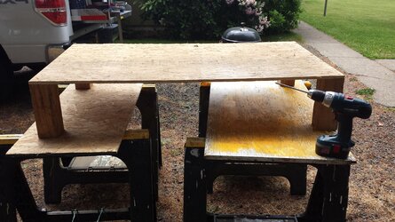
2014-06-14 12.45.45.jpg
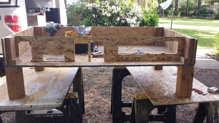
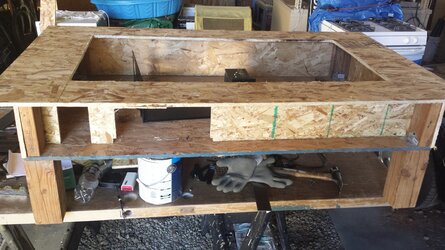
Short legs and the base. Short legs to have something there, but not full height makes for easier moving while under construction. I may have to figure a new way to attach the legs to the rest of the desk. Removing the legs currently requires striping the desk down to this level. So if I intend to take this with me when I go back to college, I either will have to work around the desk while packing the truck or find a better method.

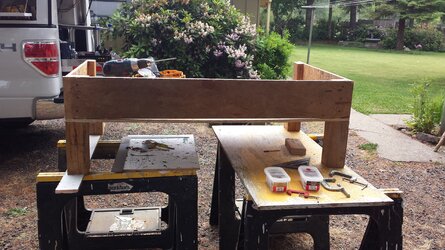
2014-06-14 14.40.484616.jpg
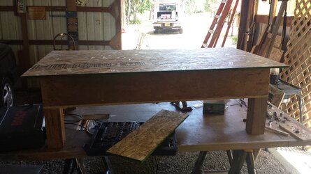
Sides attached. Similar deal here, would like to find a better way to mount the corner supports. Difference is this is primarily for aesthetic reasons. The supports are held in place by a small (1"x.5"x2") block. They look bad and get in the way.

Additionally, notice the sag in the base sheet. The side is straight, but the base doesn't have enough support towards the middle to stay flat.

2014-06-14 14.54.59.jpg
Easy enough to fix with a couple nails. Sometime in the near future will likely trade them out for some thin screws as not all the nails are holding well.

2014-06-15 17.22.44.jpg
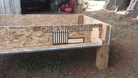
Back piece cut and placed. Who can see the reason I had room for a 480 radiator rather than the previously planned 360?

Who needs expansion slots anyway? :chair:

2014-06-16 17.31.48.jpg
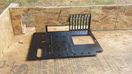
Discovered that the old Storm Scout actually has a "removable" motherboard tray and rear I/O panel. Couple holes later, the rivets are out and I don't have to worry about forgetting the slots again.

2014-06-16 17.42.26.jpg
I am aware the tray is oriented wrong in the picture. Not pictured is the back plate being flipped around so things line up properly again.

I think this initial post has gone on long enough. I have worked past what is shown so far, as I wanted to make sure it was a feasible idea before starting a log. So shouldn't be too long before I can have another update up.

One last picture to keep you interested for next time.
2014-06-28 21.51.01.jpg
 
Last edited:
Shining Light on the Situation

In the back panel shown in the initial post, I had a cutout for the PSU. Upon actually attempting to secure the PSU to the back panel ended in the mounting tabs of wood shredded. When cutting the hole I tried to take away enough so the mesh wouldn't be blocked, while leaving enough to secure it. But alas, the OSB is too weak and flaky.

So, once again the Scout went under the saw. Not much left on the poor thing to cut.
Scout.jpg
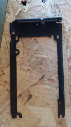
Cut out around the low portion of the back panel on the Scout and was left with a nice bracket.
PSU_Bracket-compressed.jpg
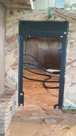
Which with a little trimming of wood fits very nicely into the cutout.
PSU_Bracket_Close.jpg
Which will make mounting the PSU a whole lot easier.


Switching gears to the picture last time and the main purpose of this update:
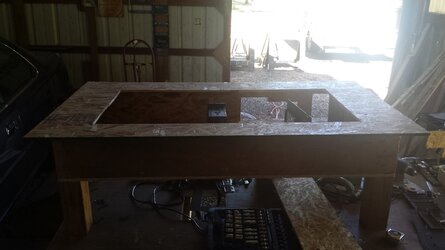
The top of the desk has a cut out for a clear panel to be eventually mounted in it. Certainly can't leave the interior of the desk dark, now can I? :thup:

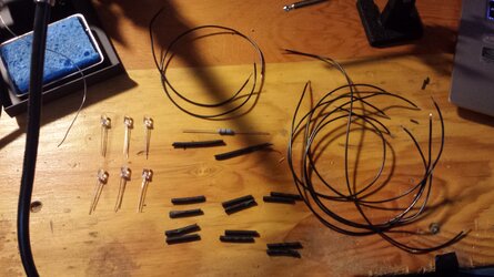
Strand_Parts-compressed.jpg
All the components to make one strand of LEDs. Total of 4 strands, 6 LEDs per strand, for a total of 24 LEDs.

Took about three hours to do all four strands, got pretty good at it towards the end.


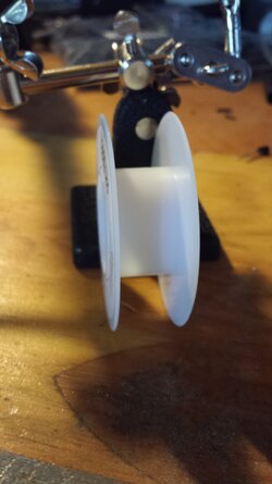
First roll of wire down. Good thing it's cheap and I bought plenty more.
Spool_1.jpg

Three hours and luckily no burned fingers later:
LED_Completed.jpg

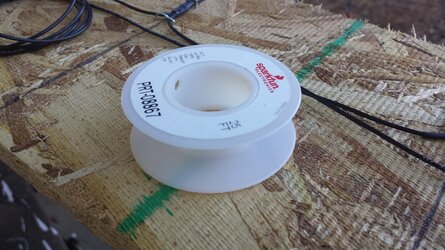
2nd (of three) roll down. Maybe I should have bought more...
Spool_2-compressed.jpg

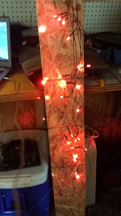
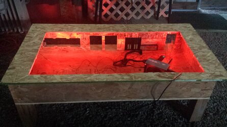
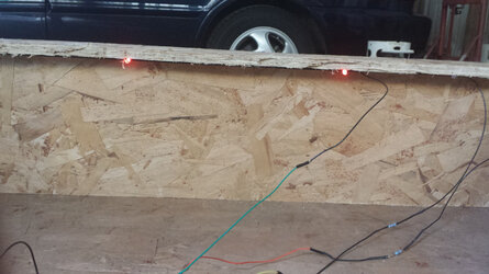
LEDs mounted on the underside of the top
LED_Day-compressed.jpg

Doesn't look too shabby. Not very noticeable though.

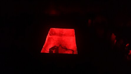
However, as it got darker...
LED_Mid-compressed.jpg


It started looking better
LED_Dark.jpg


The second part to the lighting took a bit longer, with more head scratching.
LED_Bright-compressed.jpg

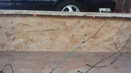
Connected to a potentiometer, controlled via PWM and a transistor, which are in turn controlled by an Arduino Uno
LED_Bright_Dim-compressed.jpg

Brightness control!
LED_Dim-compressed.jpg

Project Unity: Under Control, coming this Thursday to a forum near you.
2014-07-02 19-compressed.jpg
 
2 things for this build,

Osb will be fine, but you should put some hardwood beams underneath for truss support. Some 4/4 maple from home depot would be ideal.

Also, all this hard work... you can make it look cool too! Get some bondo and use it to seal the wood and smooth it out. Then prime and paint it. Granted I'd rather see a hardwood desk as well, but if portability is required.... that'd be insanely heavy. Also, good luck finding a piece of plexiglass that size :/


Looks cool so far!
 
A couple things.
1. for straight cuts (especially long ones) get something straight and use some clamps to hold it in place. Then just butt the saw's base plate against it, and you will get a perfectly straight cut every time.
2. Without a table saw, you will need a router to cut your recess for the viewing window.
3. For the window, I suggest that you get a pane of tempered glass cut to fit for it instead of using plexi glass. Plexi scratches easily, and will become cloudy with time. While it might cost a bit more, it will not be a whole lot more than a thick piece of plexi would be, and will look better. Just call a local glass shop to get a price.
4. you could always go the veneer route instead of buying hardwood. Most hardwood is fairly expensive, especially in longer lengths. Just a thought though.
 
2 things for this build,

Osb will be fine, but you should put some hardwood beams underneath for truss support. Some 4/4 maple from home depot would be ideal.

Also, all this hard work... you can make it look cool too! Get some bondo and use it to seal the wood and smooth it out. Then prime and paint it. Granted I'd rather see a hardwood desk as well, but if portability is required.... that'd be insanely heavy. Also, good luck finding a piece of plexiglass that size :/


Looks cool so far!

Truss support on the underside of the desk, or inside of it? I was thinking of doing underside support, then using the gap created by the support as a area for cable management. And more support internally would not hurt.

And will definitely have to try that, thanks for the tip. :) I'll see how it turns out. It's likely I'm underestimating just how heavy hardwood would be, but I don't know if it would be too bad to move. 20' to the truck/trailer to load it, then 70' or so to unload it once there. Strong friends/dolly/hand truck/casters shouldn't be too bad? :shrug:

The cutout is 40"x21". I've managed to find a panel large enough online, it's just going to be spendy for that big.

A couple things.
1. for straight cuts (especially long ones) get something straight and use some clamps to hold it in place. Then just butt the saw's base plate against it, and you will get a perfectly straight cut every time.
2. Without a table saw, you will need a router to cut your recess for the viewing window.
3. For the window, I suggest that you get a pane of tempered glass cut to fit for it instead of using plexi glass. Plexi scratches easily, and will become cloudy with time. While it might cost a bit more, it will not be a whole lot more than a thick piece of plexi would be, and will look better. Just call a local glass shop to get a price.
4. you could always go the veneer route instead of buying hardwood. Most hardwood is fairly expensive, especially in longer lengths. Just a thought though.
1. Did do that for the long cuts. Worked well for the most part. Except for the cutout where I used the jigsaw and the blade decided to wander. Trying Bob's suggestion on painting the OSB, I'll be cutting a new top and using the circular saw instead for the cutout. Need to anyways, not sure how obvious it is in the posted pictures, the the top is about 2" short. :rolleyes:
2. Have a couple options in mind. Might use a router. Or if I do a semi-vaneer route of OSB with a thin sheet of hardwood on top, cut the bottom sheet with a slightly smaller cutout to form a recess.
3. Was thinking about that. I think especially for a desktop, actual glass would look and feel better.
4. Really considering veneer right now. I'll see how the OSB sanded and painted looks then go from there. Sure would save a nice amount of money.

edit: Side question. The templates I've come across for radiator cutouts have different ones for different brands due to varied spacing. If I'm not yet sure what radiator's I'll use in future, does anybody know of any templates or means of marking where to cutout for fans so as to not conflict radiator spacing?
 
Last edited:
I would suggest that you wait until you pick up a radiator before you cut the hole for it. The only option outside of this is cutting slots for the mounting screw holes, which is a PITA and more unsightly. If you do go with glass, make sure it is tempered glass, as it is more resistant to shattering than normal glass.
 
I like this a lot. I'll be keeping an eye on it.
LED wise, I highly recommend getting a string of RGB LEDs that the arduino can control. You can get entire strips that you drive each color of every LED, or you can get the more complicated to control but much more fun individually controllable strips.
I believe there are Arduino libraries for them. I know that the strips based on the WS2801 LEDs have a library for Energia (Arduino IDE ported to run TI's Launchpad dev boards. Think Arduino, but $10 and comes with cables).

Of course, now that you've done all the wiring on the string that may not sound very attractive!
 
Truss support on the underside of the desk, or inside of it? I was thinking of doing underside support, then using the gap created by the support as a area for cable management. And more support internally would not hurt.

And will definitely have to try that, thanks for the tip. :) I'll see how it turns out. It's likely I'm underestimating just how heavy hardwood would be, but I don't know if it would be too bad to move. 20' to the truck/trailer to load it, then 70' or so to unload it once there. Strong friends/dolly/hand truck/casters shouldn't be too bad? :shrug:
The cutout is 40"x21". I've managed to find a panel large enough online, it's just going to be spendy for that big.


1. Did do that for the long cuts. Worked well for the most part. Except for the cutout where I used the jigsaw and the blade decided to wander. Trying Bob's suggestion on painting the OSB, I'll be cutting a new top and using the circular saw instead for the cutout. Need to anyways, not sure how obvious it is in the posted pictures, the the top is about 2" short. :rolleyes:
2. Have a couple options in mind. Might use a router. Or if I do a semi-vaneer route of OSB with a thin sheet of hardwood on top, cut the bottom sheet with a slightly smaller cutout to form a recess.
3. Was thinking about that. I think especially for a desktop, actual glass would look and feel better.
4. Really considering veneer right now. I'll see how the OSB sanded and painted looks then go from there. Sure would save a nice amount of money.

edit: Side question. The templates I've come across for radiator cutouts have different ones for different brands due to varied spacing. If I'm not yet sure what radiator's I'll use in future, does anybody know of any templates or means of marking where to cutout for fans so as to not conflict radiator spacing?

Here's a suggestion from a body man, since you might use bob's suggestion of Bondo and paint; Don't use Bondo. Go with Evercoat Z-grip. Bondo gets very hard when it kicks off. Z-grip stays soft enough to sand out much easier for about a day, then it gets really hard. It's also easier to spread and has less pinholes.

People go by the brand name too much when in reality Bondo is some of the worst filler there is... ;)
 
I've never had any issue with bondo myself, but I'm always willing to try something new out. Done right, bondo would be fine though, even though there may be a superior product.

Personally, I only use bondo on woodworking projects, and every time I've tried a "superior product", a lot of the time I'm sitting there wondering "how?"
 
I don't do wood working but I've tried many different types of filler, and by-far the two best I've used are 3M and Evercoat. I wasn't trying to say Bondo is bad, I was just trying to say there's much easier products to work with. ;)

I've converted more than a few people to start using superior products.
 
Ah don't get me wrong, I'm not even close to saying bondo is the best. It's just extremely cost effective, and for this type 99 use will be completely fine. I just have a hard time justifying the cost of some of these products lol. The 3m gold stuff is great, very easy to sand, but is it worth the double cost for this type of thing?
 
The Z-grip is only $5/gallon more than Bondo and still sands like a dream... although not nearly as easy as that 3M gold. I've only used samples of that given to us by our jobber but I'm sure it's even more expensive. But the Z-grip is still by-far my favorite. Keystone makes one very similar to Z-grip but it has more pinholes, otherwise it's just as easy to sand and I think it was cheaper too... may even be cheaper than Bondo too! I will say to stay far, far away from the NAPA branded stuff; that's the worst I've ever used. :chair:

Anyway, I can't wait to see what WarWolf does with this. I've always loved the computer in desk idea, but I don't think I'd do it myself.
 
Pull the Third Lever

Thanks for all the comments and suggestions, keep them coming. :thup:

Meant to get this out yesterday, but got busy and tired. So here it is now.

I decided before moving too much further with the electronic portion of the project, it would be best to create the control panel.

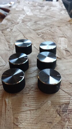
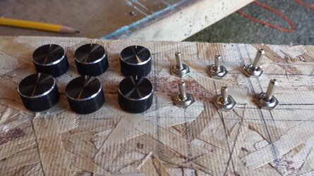
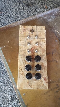
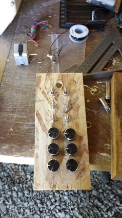
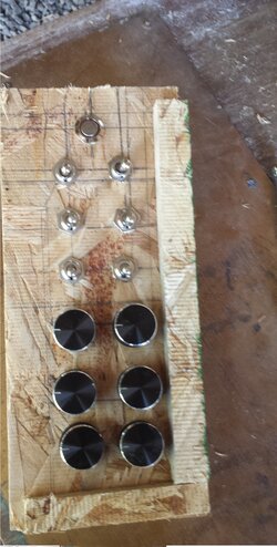
Started with the dials, control for fans (x3), speakers (x2, volume/bass), and LED brightness (x1)
Dials.jpg

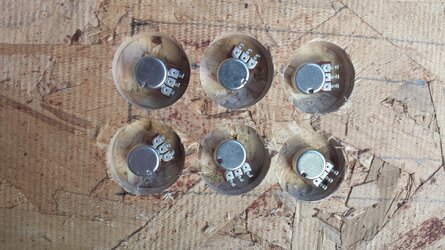
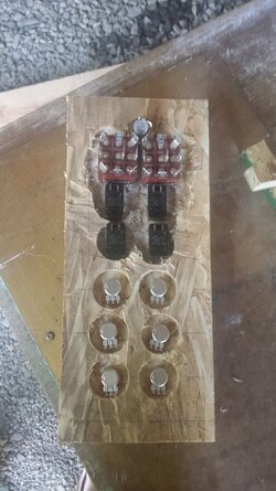
Had to use a forstner bit to drill into the wood a small amount to allow the potentiometers to extend through enough for the nut to catch.
Pots-compressed.jpg

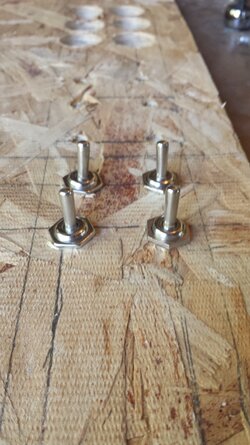
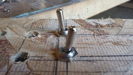
Continued on to the toggle switches, speakers (x1), fan control (x1, auto or manual), reservoir light (x1, for future), mute (x1, possibly)
Toggle.jpg

Did a similar hole on the underside for the toggle switches as for the dials.
Dials_Switches-compressed.jpg

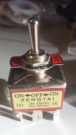
Not sure the official name for the next ones, three-way switches? ON-OFF-ON style, can flip two directions.
2014-06-18 19.20.30.jpg

Only two of these, light control (x1, second mode coming soon), touch screen(x1, possibly)

Dual_Toggle-compressed.jpg

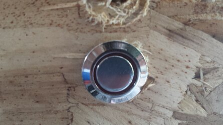
And finally, decided to include the power button here as well.
Using a 16mm button illuminated by a red LED.
Button.jpg

And finally, here's everything all together.
Fin.jpg

The back
Fin_Back.jpg

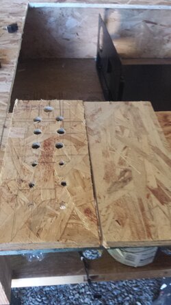
Proving cheap wood was a good idea, the progression of holes:
Progression.jpg

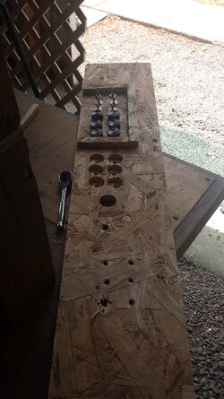
Last portion of the panel is cutting spacers for it.
Fin_Recess.jpg

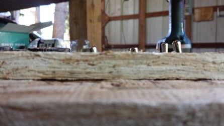
The idea behind this is to place the controls at the level of the desktop.
Recess-compressed.jpg
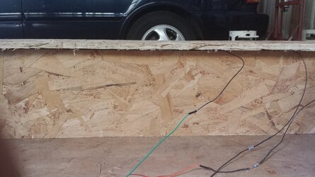
Luckily, from the top of the highest switch down to the panel is 28/32". So to cover that I need a spacer 28/32" - 7/16" (thickness of the desktop itself) which comes to a nice 14/32", or 7/16". Which coincidentally is the thickness of the OSB.

I will very likely re-make this before mounting it. The mounting holes are drilled into the smooth side of the board, which means the controls are on the rough and uneven side. As you might be able to see, the bottom row of dials are slightly askew, one is at an angle and another is wanting to push through.

Any of the controls with a (possibly) are there for use with a possible future feature. Whether or not they actually happen, we shall see. Even if they aren't used for their original purpose, they can always be used for something else or just sit there looking good.

Decided it was also a good time to cut a new top and size it correctly this time. Hoping to finish it today.
2014-07-04 13-compressed.jpg
 
Single pole, double throw switches.

Was wondering it they'd have a have a different name, thanks.


No one main focus for this post. Jumped around a bit on what I was working on as needed. Cut a new top as the old one was mis-sized, changed the mounting method for the interior corner supports, swapped the bottom nails for screws, and a cleaner control panel.

Starting off with the top,
Top_New_compressed.jpg

Uncut_top.jpg
Fits better with more overhang. The hole on the first top was cut too far back so either the back panel was easily visible or the top didn't cover the entire top. New top was properly measured, with more uniform overhang.
Top_Cut.jpg
Top_Cut_Back.jpg


Got an only slightly banged up box today.

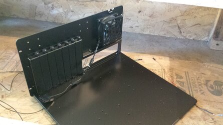
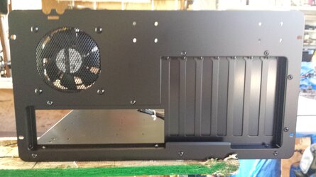
Gave in and bought a motherboard tray with the rear I/O panel attached.
Mobo_Top_compressed.jpg
Trying to get the tray and I/O panel from the Scout to line up and mount correctly was not going so well. Either the spaces was too narrow between the edge of the motherboard and panel when it was mounted on the tray, or the location to attach the tray would seem to wander.
Mobo_IO_compressed.jpg
Nice and easy alternative from Lian-Li. Not planning on keeping the fan, but the tray should work well.

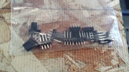
Also in the box was a handful of 4-pin fan headers. Don't need these quite yet but I figured why not while I already had an order going.
Fan_header_compressed.jpg


Corner_Support.jpg
Found out the desk was not very straight. A main culprit being the corner supports were not being held perfectly upright.

Some how the pictures I was sure I took failed to appear. :screwy:
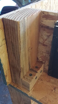
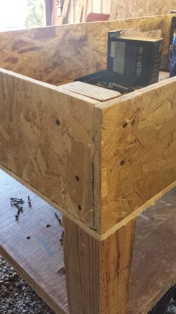
At the intersection of the two sides is now a metal corner bracket to hold them at a nice square angle. The screws going through the side and into the bracket continue into a 2x1 block. The 2x1 block then has a bracket (visible in picture below) at its base securing it to the base of the desk and leg.
Top_Cut_Back.jpg
Corner.jpg
While still not perfect, it is much better than before.
Will take pictures to replace those that disappeared soon as I get the chance.


Cut a new control panel.
Panel_New.jpg

Much smoother, dials turn nicer
Panel_New_Cut.jpg

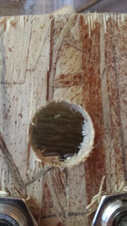
Only issue is I cut the hole for the power button just a hair too close.
Power_Hole.jpg
At the bottom the edges from the two double throw switches just barely interfere with the button going all the way in.


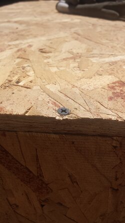
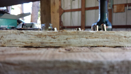
Finally got tired of the nails holding the base snug to the sides sagging and swapped for screws. Easy and quick change, pulled the nails, put screws in their place. Holds much better.
Bottom_Screw.jpg


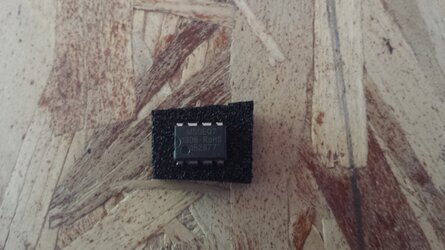
Next update (or two, depending on if I combine them or not) should be pretty good ones.
Chip.jpg
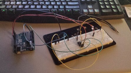
Back to the breadboard! :clap:
Breadboard.jpg
 
Back