• Welcome to Overclockers Forums! Join us to reply in threads, receive reduced ads, and to customize your site experience!

Refurb and modify a Cisco Catalyst 3560 PoE-24.

Overclockers is supported by our readers. When you click a link to make a purchase, we may earn a commission. Learn More.

don256us

Uber Folding Senior
Joined
Jul 17, 2003
About a year ago I bought an old and very used Cisco Catalyst 3560 PoE-24 switch. While I had mounted it and turned it on, I never really did anything with it at all. More recently, I got a Ubiquity PoE AP and thought that this would be the best time to put my switch into production. I mounted the switch in its new home and turned it on. TOO LOUD! It is way too loud for me to have on 24/7.

I started to research replacing the fans and came upon the Noctua NF-A4x20 FLX as a proper replacement. Note: The FLX designation is important to anyone looking to do something similar.
IMG_20180117_174305.jpg
IMG_20180117_174316.jpg
IMG_20180117_174341.jpg
IMG_20180117_174416.jpg

I compared it to the old one.
IMG_20180117_174525.jpg

The old fans are 40x40x40. The new fans are 40x40x20. No problem.
IMG_20180117_174612.jpg

Make sure to note the direction of air flow.
IMG_20180117_174453.jpg

I took a sound reading using a free phone app and had a reading of around 65 dBa. I simply plugged in the new fan and without using the meter, I assure you that it emitted 0 dBa. That is a huge difference. Multiply that by three and you can see the benefit. But alas, While the plug is the same, the pin-out is different. Not to worry, I knew this already.

First I took out the "extension" cable that came with the Noctua fans.
IMG_20180117_181112.jpg

Lets be blunt here. I had to cut some cable but I didn't have it in my heart to cut the cable on my brand new fans. I removed the female end of the extension cable.
IMG_20180117_181147.jpg

I removed the insulation to see the wires themselves. Unlike the other tutorials that I found, the colors of my new and old fans were the same. I took a chance and connected yellow to yellow, black to black and red to red.
Note: The Noctua fans came with four scotch locks each so this was easy easy easy.
IMG_20180117_181306.jpg
IMG_20180117_181408.jpg
IMG_20180117_181508.jpg
IMG_20180117_181547.jpg

I then reinstalled all three fans and powered the unit up. Worked like a champ. The sound meter showed a level of about 45 dBa. I am going to state that I do not know what the actual sound reading is. 45 dBa is just a number with no real backing to it. What I will say is that it was very loud once it got up to temp and now it is not. I will not be putting this unit to hard use. It will host my AP and my folding farm and provide me an opportunity to play with a live switch.

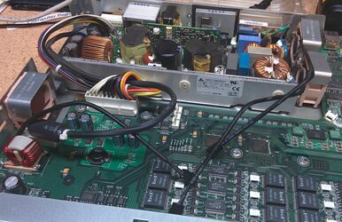
Here is a shot of the "completed" project.

IMG_20180117_175510.jpg

As a final note, I also recieved my new soldering station today. Once I recap the unit, I will remove the scotch locks and solder the wires together and heat shrink them. (Who am I kidding. I'll just tidy the wires up with zip ties and forget about it.

I still have to recap the unit as I have four caps that are buldged. I will add that when I work on it. Maybe this weekend.
 

Attachments

  • IMG_20180117_175500.jpg
    IMG_20180117_175500.jpg
    1.4 MB · Views: 2,038
Last edited:
Now for the refurb part. Several members here helped me pick out the proper caps and a soldering station. Here is what I did:

First. A big "Thank you" for this purchase.
IMG_20180120_115908.jpg
And these:
IMG_20180120_115858.jpg

With these on hand and with the confidence that these recomendations gave me, onward I went.

First I removed the rack mount brackets and all exterior screws. No pictures needed here. I will say that the fine threaded machine screws are for the back and the course threaded screws are for the sheet metal on the sides. Just note that.

Remove the top cover to revieal the guts.
IMG_20180120_160833.jpg

WARNING
Note that there are at least five (5) clear plastic light bender thingies. These sit over LEDs and bend the light to the front pannel. They clip in. You have to compress the clear plastic clips to remove them from the motherboard. They WILL snap if you do not take time to pry them gently and eavenly. Do not in any way force these. Here are the best pictures that I could take to illustrate what I'm trying to say.
IMG_20180120_155012.jpg
IMG_20180120_155041.jpg

The two "big" units that show the individual ports status must be removed prior to removing the mother board. The other three can probably wait until the board is removed.

Unplug the fans and power connectors.
IMG_20180120_112713.jpg
IMG_20180120_112818.jpg
Be careful here too. The plastic is brittle after years of heat.
IMG_20180120_112827.jpg

Now you can remove the 15 screws that hold the motherboard to the chasis. There is only one item of note. One screw also holds a clip for a zip tie to hold fan cables.
IMG_20180120_112918.jpg
This is not a big deal but you do want to put it back.

It took great care to remove the board as the three remaining clear plastic light bender thingies were still up against the front panel.
Here are some shots of the five caps to be replaced. Three were buldged and two looked fine. All were replaced.
IMG_20180120_113432.jpg
IMG_20180120_112904.jpg

First, remove the old caps.
IMG_20180120_122919.jpg

Then install the new caps.
IMG_20180120_135433.jpg

Of course I'm glossing over the fact that this took the most time. Plus I really butchered it up. Unfortunately I didn't take any shots of my shotty work. Huh? Mystery that.

When putting everything together, pay attention to the power wires. I didn't tuck them in on my first try and really fought with it.

So the final question: Did it work?
Well, the fans are nearly silent in my basement environment so that is a 👍
The switch does seem to power up and may be working great.

The next question is: How do I not know if it is working?
I could plug it in and connect it to my unmanged switch and access the web page but I didn't. I'm waiting for my serial to USB adaptor to arrive from China to connect via the console port. I do expect one problem

Wait what?! You expect a problem?
Yes. The middle fan wire for the stock fans and the replacement fans work in very different ways. I expect the Cisco switch to tell me that the fans are dead. There is a very simple fix which is to short that pin to ground. I will do that once I get some testing done to ensure that it is working. At that time, I will shorten my fan leads and and tidy it all up inside.


Costs:
1 x used Cisco switch from eBay. $30 shipped.
3 x Noctua NF-A4x20 FLX fans from a Newegg 3rd party seller. $42 shipped.
10 x 1800 uf 6.3v 105c caps from digikey. $10 shipped.

All said and done, I could have my own PoE Cisco brand 24 port switch for $82. The bulk of the price was to switch out the loud (working) fans for silent fans that will fit my needs.
 
Last edited:
looks like a 100meg 3560, good job regardless! the 3560G does not have caps and has a stand alone injector board of some sort.


i had to re cap a 3560 at work before, those were notorious for that and those 20mm fans screaming with bad bearings.
 
looks like a 100meg 3560, good job regardless! the 3560G does not have caps and has a stand alone injector board of some sort.


i had to re cap a 3560 at work before, those were notorious for that and those 20mm fans screaming with bad bearings.
Yeah it is just 100mb. Aside from my AP, it will house my folding farm and unused server. I still don't know it's working condition as I have not connected it up.
 
if anything, my guess would be fan errors in console.

Absolutely. I have to short out the center pin on each fan to ground. After I test it, I will double check my facts and modify the fan pin-outs.
 
Update.

I finally got my USB to serial cable and connected it all up. As expected, I got failure notices about the fans. I did some goofing around and got them all wired up. I had two of the three done up with shrink tube and everything. I plugged the unit up and


POP!

Some damn VRM or whatever blew. It left a nice burn mark too. I just PO'd right now. I unplugged it, turned off my music, turned off the light and I am now sulking in my upstiars office like a little kid.
 
I haven't forgotten about this thread. I replaced the blown part after
1) figuring out what it was.
2) Finding where to get this discontinued part. (alibaba)
3) buying a soldering station. Thanks to help from this forum.
4) figuring out how to remove and replace said part. (480c blow gun on above mentioned soldering station.)
5) having the replacement part burn after the fans were connected.
6) Findning a new wiring that does not blow the part and causes the new fans to run.

I might be near complete. I'm getting ready to head into my workshop and run the switch with all three fans. I'll have to relearn how to program a Cisco switch from scratch as it has been too many years since I had a class on it.


sorry i havent been around lately lol, holy crap you have had issues. what part blew up? i'm wondering if the fans pushed out too much amps?


either that or your wiring was bad and shorted out the circuit. dont you love hot air :p i hate it, but i've been getting better at replacing quad flat packs myself, and playing with fixing things i only have one working part of.
 
I do have the information and pictures but I haven't updated this thread. I'll do that. The switch has been working great for a while now and I can't hear it at all so that's a huge plus.

Hi. So it happens that I have same model of Cisco switch which I need to make less loud. I did choose same Noctua fans as you used. After I destroyed one plug I discovered that it is quite easy to pull off the wires from the plug and put them in again with the correct order (correct for Cisco switch). Fans are working but I do get warnings from IOS. Could you share how your wiring looks like at the end, and if you figure out how to get rid of IOS warnings? Did the idea of shorting the tacho wire to the ground caused the motherboard part failure?
 
Last edited:
Back