• Welcome to Overclockers Forums! Join us to reply in threads, receive reduced ads, and to customize your site experience!

PROJECT LOG Slatted wood storage server and HTPC

Overclockers is supported by our readers. When you click a link to make a purchase, we may earn a commission. Learn More.

popenz

Registered
Joined
Jan 28, 2013
Location
San Francisco, CA, USA
First-time caller, long-time listener. I've pulled a lot of inspiration from the projects that you guys and gals have made on these forums, and so I'd like to share one of my own. I hope you like it.

I have done quite a bit of research to find a replacement solution for my aging Infrant ReadyNAS, and I quite like the idea of making it into an HTPC too. I won't go deep into the requirements, but a high level summary:
  • Silent and inconspicuous case: It will live in the living room, but I don't want to see it. I'm not a fan of flashy PC setups or blue LEDs.
  • Low power: SSD root drive, spin-down disks, disable cores, etc.
  • Reliable storage: It should house at least six 2.5" drives for RAID storage.
  • HTPC: It should be reasonably powerful and have high audio output quality.
I found some pre-made cases that I liked, but they are either too expensive or too large. They are Streacom FC5 Evo WS, HDPLEX H5.s and Fractal Design Node 304.

I decided to build my own case, as a fun project. The design had to be relatively simple because I don't have access to a descent workshop - only some tools in my apartment.

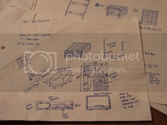
Here's a drawing that kind-of describes the layout and the slatted-wood look that I am aiming for. You can see that it describes a metal tray to mount the computer hardware, and a slatted wooden shell to cover the whole thing. The idea is that the slats will allow heat to escape, as well as looking nice.
Post1-1.jpg

Some of the project is already complete (thanks to a long weekend) to I'll add a few posts immediately, and will try to remember all the little niggles I encountered along the way. After the build, this log may continue into some power and cooling optimizations (I have a feeling that I won't get it right the first time).

Cheers!
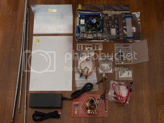
 
Shopping list

I bought most of the hardware required before I even started the project. This may have been a little foolish, but whatever; I was excited.
Post1-2.jpg

The case shopping list: (please forgive the mixing of imperial and metric units!)
  • 10x14" galvanized steel sheet and 5x5x10" 90˚ step shingle (ducting section in hardware store). I was going to cut and bend an oven tray, but these were already the perfect size!
  • Some adjustable steel cross-bars from an Ikea bed - perfect for drive rails. Found on the street :)
  • 12m of 12x18mm pine wood.
  • 3m of 6mm diameter doweling.
  • LEDs, power button, screws, nuts, etc.
The computer hardware shopping list (for those interested):
  • picoPSU-160-XT with 192W fanless power supply.
  • Intel DH77DF Mini-ITX motherboard.
  • Intel i3 2120 CPU (65W max). A 2100T would have been a better choice, at only 35W max.
  • Kingston HyperX 8GB (2x4GB) DDR3 kit.
  • Crucial 128GB m4 mSATA SSD (CT128M4SSD3).
  • Syba 4 channel PCIe SATA-II controller (SY-PEX40008) and a PCIe 4x extender cable.
  • 5x Western Digital Blue 1TB 2.5" drives (WD10JPVT).
  • HRT Media Streamer+ (USB DAC).
  • Cables, etc.

Next post begins the actual build...
 
Last edited:
Screw holes, cable-routing holes, other holes...

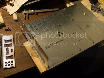
The first part of the build is to drill the tray in preparation for the computer hardware. The holes will also support cable ties for cable routing.

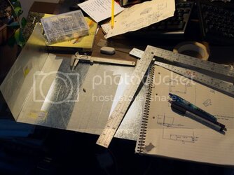
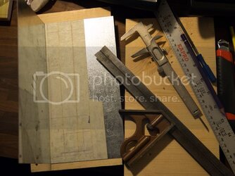
Beginning the measurements, using Vernier calipers with the Mini-ITX and ATX specification documents. Pencil etchings on masking tape worked well.
Post2-1.jpg
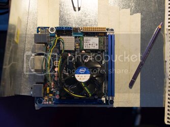
Verifying the motherboard screw holes.
Post2-2.jpg
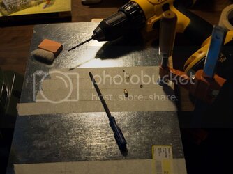
Testing the drill bit. The hole was clean, and supported the motherboard header and the nut underneath.
Post2-3.jpg
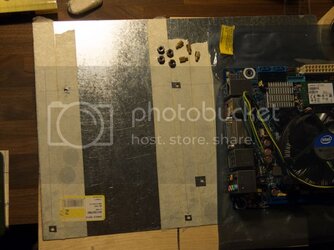
All motherboard holes drilled, and the motherboard fits perfectly. The nut is a stainless steel 303 #6-32 hex nut. The motherboard sits against the rear edge close enough that the rear ports will be properly accessible.
Post2-4.jpg
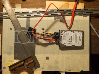
First measurements for the drive rails. I measured directly against a 2.5" drive, since I wasn't completely sure of the detail.
Post2-5.jpg
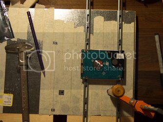
This is how the bottom rails will be mounted, although the drives will sit upright. The rails are cross-bars from an Ikea bed - I found them on the side of the street. Their measurements are almost perfect for this purpose!
Post2-6.jpg
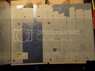
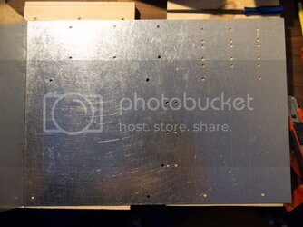
All holes drilled to mount the motherboard, drives, power supply and cable guides. Some of the measurements were exact, some not so exact :p
Post2-7.jpg
Masking tape removed - this is the end result. Enough space has been left on the sides to slide into the tray guides that I'll make in the wooden shell.
Post2-8.jpg
 
Cutting metal

Using a rotary tool to cut metal still gives me a kick, though I know it's probably boring to most you reading this.

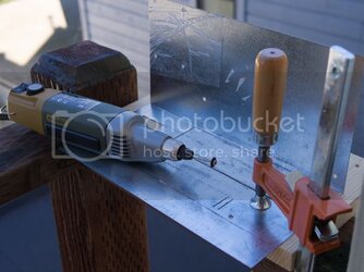
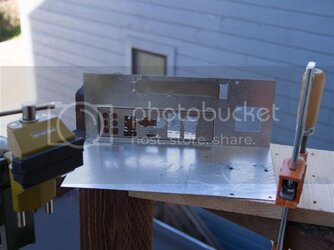
In this post I'm preparing the rear of the system tray, including cutting the rear ATX port mount.

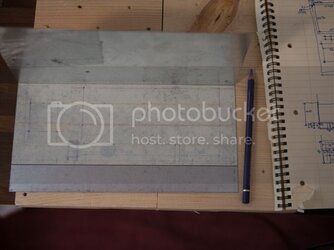
Beginning measurements for the rear of the system tray.
Post3-1.jpg
All measurements are complete - ready to cut!
Post3-2.jpg
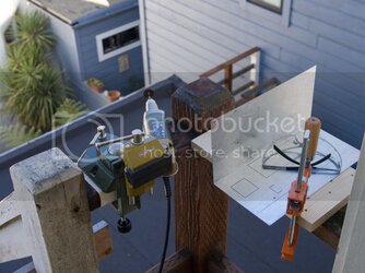
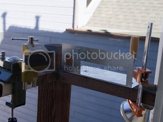
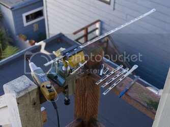
Prepping for the first cuts. I'm on the rear stairwell of my apartment in San Francisco. Nice views for cutting metal!
Post3-3.jpg
Progress.
Post3-4.jpg
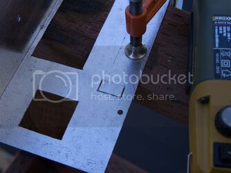
All cuts have been made, including the rear ATX port bay, power supply connector holes, expansion card mounts. I really should have drilled the hole for the expansion card screw before I cut this part out - I had to drill it later.
Post3-5.jpg
A close up of the cut for the expansion card fixture.
Post3-6.jpg
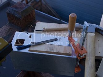
Bent out the expansion card fixtures. For the panel foot, I hammered the guide into a hole that I chiseled out of the wood.
Post3-7.jpg
Testing the ATX rear panel mount, and the expansion panel mount. All good.
Post3-8.jpg
Mounting all the headers required for the motherboard and hard drive rails. This is also the time when the steel sheet and 90˚ edge sheet were joined.
Post3-9.jpg
Testing the motherboard, hard drive and expansion card mounts. Happy so far, but I forgot to cut the drive rails.
Post3-10.jpg
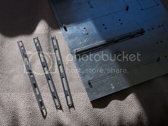
Converting some Ikea bed rails into Western Digital hard drive rails.
Post3-11.jpg
Hard drive rails completed.
Post3-12.jpg
 
Got wood?

Now I'm building the wooden shell of the case, which will house the metal tray that I prepared earlier. The tray should slide in, and be held in the space between the bottom two slats on each side.

Unfortunately it didn't quite go to plan - I had to modify the design because I couldn't achieve what I wanted to with the tools I had available. I'm obviously not the world's greatest carpenter, but I'm learning as I go ;)

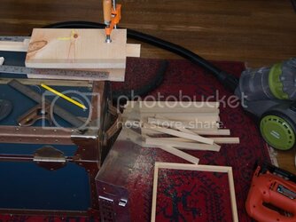
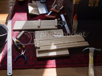
After measuring up the tray and preparing measurements for all of the wood pieces, I started preparing the wood slats in the living room of my little apartment. The wood is 12x18mm, probably pine.
Post4-2.jpg
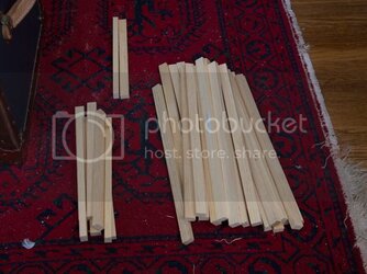
This is what naked slats look like.
Post4-3.jpg
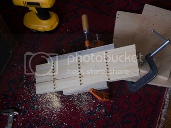
My plan was to tunnel doweling to join the slats into wooden boards, so I measured the holes and drilled them all. I quickly realized that the holes were all imperfect (I don't have a drill press) and I could barely join two of them together with the doweling, let alone the seven that I wanted for each wall. I tried drilling two lengths that were clamped together, which worked ok but greatly increased my chance of drilling through the side of the wood, and ruining the look.
Post4-5.jpg
I decided to join the bottom two slats of the front and both sides, so that I could use the space between the slats to hold the metal tray. The rest of the slats would be held together with interior braces. I needed to measure the brace-placement carefully, because they encroach on the interior space and could make it difficult to place the motherboard, PSU, etc. I tried to maintain a constant 2mm between the slats.
Post4-6.jpg
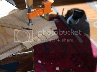
Since the tray is wedged between the bottom two slats, I needed to make the rear of the tray fit in. I considered either trimming the metal tray or chiseling out the wood (like I did). I realized half-way through that I could have just cut a slit down the slats that the tray would rest in - I didn't need to chisel a chunk out of each slat. Oh well.
Post4-7.jpg
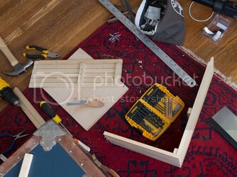
One side attached snugly to the front.
Post4-8.jpg
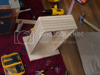
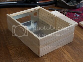
Both sides attached. Getting an idea of what it looks like now.
Post4-9.jpg

Kind of funny - m'lady just arrived home to a bombsite in the living room. Obviously wasn't too impressed, but she let's me get away with it.
:chair:

More pics to post soon...
 
Slide tray A into slot B

Continued from above...

The tray fits in snugly, but I definitely need to fix it in properly.
Post4-10.jpg
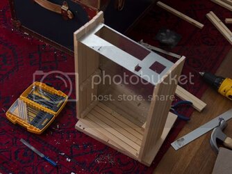
The bottom rafters were installed to keep the sides fitting snugly to the tray. The tray can still slide out the back at this time.
Post4-12.jpg
So far so good.
Post4-13.jpg
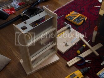
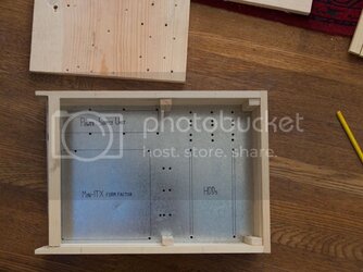
Birds eye view. You can see that the side-brace placement was pretty important.
Post4-14.jpg
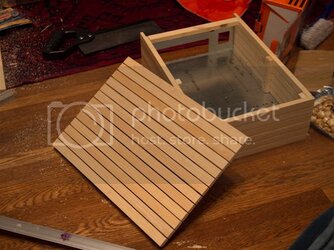
I made the lid in the same way as the sides.
Post4-18.jpg
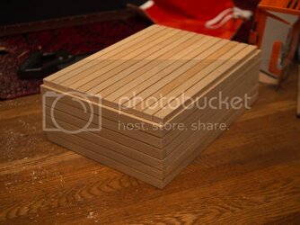
Mostly complete. Unfortunately, because of the design changes, the ends of the lid slats are visible from the front (they were meant to be hidden behind the top slat of the front panel). Also, the lid isn't flush with the front and sides. Oh well.
Post4-19.jpg
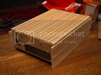
The tray isn't fixed into the case at this stage, because I still need to oil the wood. I had planned to just put a few screws in the top of the rear panel, but the bottom will also need support because the metal is a bit too flexible. I'll use a few more braces.
Post4-20.jpg

You can see that some of the design changes have been a little bit frustrating,
and I got to the point where I just wanted to keep chugging along instead of finding someone with a drill press to help me out.

So, next I'll oil the wood and fix the tray in place...
 
A lick of oil

Post5-1.jpg

Post5-2.jpg

Post5-3.jpg

The colour was a bit lighter than I hoped for, but that's what happens when you use the remnants of wood oil you had in your toolbox.
Post5-4.jpg

I locked the tray in with a few posts, that also help to keep the slats aligned. It looks like crap, but nobody will be viewing the rear of the case. I also installed a very basic power button.
Post5-5.jpg
 
images are broken upload the pics to the site this is an awesome build!
 
Finally

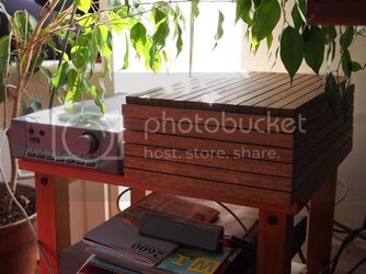
View of the case next to my amp. There is a yellow LED that shines a sliver of light between the bottom two slats. You can see the HRT Music Streamer+ DAC that I found for a good deal on eBay - it sounds amazing - way better than a nuForce uDAC-2 or Apple AirPort Express, in my opinion (I own both of these also).
Post1-3.jpg
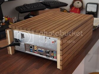
The rear is not very interesting, although I'm pleased that the ATX rear panel fits so snugly.
Post7-2.jpg
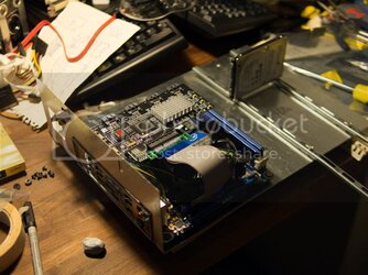
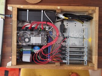
Internals. Adorama still haven't delivered my 5th 1TB drive after 5 weeks of waiting, but I'll get it in soon.
Post7-1.jpg
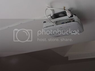
And the projector. It's only 720p but it's small, light and relatively quiet.
Post7-7.jpg

I've noticed that the PSU makes little sparky sounds when the PC is off - I assume that this is the switching circuit because it's fine when the PC is on. The PSU block and RAID controller also get very hot, heating the wood above, but I fixed that by adding a silent 80mm PWM fan. I'll post more about this later, with my power measurements.
 
Last edited:
I think my favorite thing about this build is how well it fits in to its surroundings, bravo good sir.
 
Back