• Welcome to Overclockers Forums! Join us to reply in threads, receive reduced ads, and to customize your site experience!

how to enable 512KB cache for an unlocked green thornton

Overclockers is supported by our readers. When you click a link to make a purchase, we may earn a commission. Learn More.

coscos

New Member
Joined
Dec 19, 2003
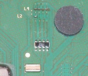
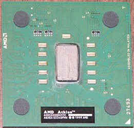
Just got a AQXEA 0334 green thornton. Tried on A7N8X DLX and it is unlocked! However, I tried to enable the 512KB cache but failed. The L2 bridge looks different from the article on xi labs.

Can anybody give me a clue how to enable the 512KB cache? thanks. I will upload some picture of my CPU if necessary.
 
On the green package the bridges are covered with a thin layer of plastic, so if you just use conductive paint on top of that it won't contact them. You need to gently scrape off the plastic top first and expose the tracks underneath.
 
stamasd said:
On the green package the bridges are covered with a thin layer of plastic, so if you just use conductive paint on top of that it won't contact them. You need to gently scrape off the plastic top first and expose the tracks underneath.

could you give me more detail? how to do that?

By the way, here the pictures for my CPU and L2 bridge:
(AQXEA 0334 SP MW)
 

Attachments

  • l2.jpg
    l2.jpg
    31 KB · Views: 230
I missed that the processor is unlocked in your initial post.

Is there a "Fake PCB" covering the bridges? If so, then dig it out with a thumbtack to gain access to the L2 bridges you need to connect. Since there is "Fake PCB" material covering the fround plate, and burn, between the bridges, you can just connect the L2's with conductive ink, or Window Defogger Repai Paint.

In the bridge picture you attached, the L2 bridge (the first one from the left) that has the burn mark (visible as a little brown rectangle) betwen the two little gold dots is the one you need to connect. The burn mark has a ground plate below it, and you need to make sure that you *DO NOT* connect either of the bridges to that plate when shorting the L2 bridges.

If there is no "Fake PCB" then you need to fill the Burn hole with White-Out, and let it dry (leave the two golden dots uncovered). Then use conductive ink, or "Quick Grid" Rear Window Defogger Repair Paint to connect the two little golden dots. Let that dry, and then test it out. If it worked, and the full cache is available, then you might want to seal the bridges with some more White-Out, or with some clear Laquer.

Good luck! Tell us how it goes! :)
 
Last edited:
If I'm not mistaking, judging from the pics that you uploaded, you just filled the gap with conductive material, right???

If this is so, then it's no wonder that the mod didn't work! Take a look at this howto and then try the mod again:

http://www.ocprices.com/?rev_id=184

This method worked for me on one Duron and 3 Thortons already.

But keep in mind that you could also have a chip with defective cache.

Greets

Ingmar :)
 
I filled the gap and I connected the two pads with conductive ink. In order to take a picture, I removed the conductive ink. That's why you didn't see it there. Thanks for the reply though

Celemine1Gig said:
If I'm not mistaking, judging from the pics that you uploaded, you just filled the gap with conductive material, right???

If this is so, then it's no wonder that the mod didn't work! Take a look at this howto and then try the mod again:

http://www.ocprices.com/?rev_id=184

This method worked for me on one Duron and 3 Thortons already.

But keep in mind that you could also have a chip with defective cache.

Greets

Ingmar :)
 
Just read the link you gave, very helpful information. But I am a little bit comfused: if we scratch the laser hole untill we see the copper, and fill it with conductive ink, then why not fill the hole directly? Also, after we see the copper, do we still need to fill the gap with some inconductive filler?

thanks.

Celemine1Gig said:
If I'm not mistaking, judging from the pics that you uploaded, you just filled the gap with conductive material, right???

If this is so, then it's no wonder that the mod didn't work! Take a look at this howto and then try the mod again:

http://www.ocprices.com/?rev_id=184

This method worked for me on one Duron and 3 Thortons already.

But keep in mind that you could also have a chip with defective cache.

Greets

Ingmar :)
 
felinusz said:
I missed that the processor is unlocked in your initial post.

Is there a "Fake PCB" covering the bridges? If so, then dig it out with a thumbtack to gain access to the L2 bridges you need to connect. Since there is "Fake PCB" material covering the fround plate, and burn, between the bridges, you can just connect the L2's with conductive ink, or Window Defogger Repai Paint.

Does that mean I don't have to fill the gap with any inconductive filler? So I can apply the conductive ink directly (after the digging)?


In the bridge picture you attached, the L2 bridge (the first one from the left) that has the burn mark (visible as a little brown rectangle) betwen the two little gold dots is the one you need to connect. The burn mark has a ground plate below it, and you need to make sure that you *DO NOT* connect either of the bridges to that plate when shorting the L2 bridges.

so I'd better fill the hole first and then connect the L2, right?


Good luck! Tell us how it goes! :)

I'll try it tonight and let you guys know. thanks.
 
Let me try to explain what you have to do. You gotta get some Conductive material (to connect the dots) and some NON-Conductive material (to fill the pits). Then carefully scrape away using a pin the dark green dots till you see copper, when you're able to see the cooper on both dimm (the inner) dots then clean the bridge up w/ some acetone, fill the pit and the close up the bridge with conductive material
 
coscos said:
Does that mean I don't have to fill the gap with any inconductive filler? So I can apply the conductive ink directly (after the digging)?[?QUOTE]

No, you still need to fill the little brown burn hole with non-conductive material to avoid killing the processor.

coscos said:
so I'd better fill the hole first and then connect the L2, right?

Yes - exactly. Fill the hole with non-conductive material. :)
 
You don't need any non-conductive filler at all if you use the method that is described in the link I gave to the ocprices.com site. You just have to scratch the edges of the little laser cut pit a bit, until you see the copper shining. Then clean the pit ad then just fill it up with conductive material.
That's all! Worked for me on 4 CPUs already ;) No need to do it in a more complicated way.:)
 
finally got a chance to post my result! I got a 512K L2 cache now! see the screenshot of cpuz.
cpuz-512k.jpg


I created a visual instruction at my homepage . hope it is helpful to others.
 
by the way, anybody where to get an extra side panel for my case? it is a Enermax CS-1251-B.
 
Back