• Welcome to Overclockers Forums! Join us to reply in threads, receive reduced ads, and to customize your site experience!

Repairing a physically damaged 290X

Overclockers is supported by our readers. When you click a link to make a purchase, we may earn a commission. Learn More.

Fever

Member
Joined
Sep 16, 2002
Location
Montreal, Canada
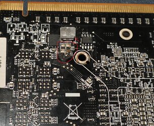
Anyone know if it would be possible to repair this damaged card? I'm thinking Bobnova might be the man for the job.

Yy6cv6q.jpg

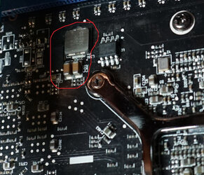
EgQbQzB.jpg

If you think you can fix this for me, let me know the cost and we'll get the boll rolling.
 
Top photo is an easy fix, two new 16v ceramic caps and its set.
Bottom photo could be a problem, can you find a photo of that area on an undamaged card?
It looks like a couple things may have been torn out and taken their pad with them, that's a much trickier fix.

Accident when removing heatsink/waterblock?


EDIT:
Found a photo, two resistors and their pads got scraped off. This is a complication.
I can almost certainly get two new resistors to attach, the problem is what resistance they were. To tell that I would need an undamaged card to take the resistors off of and test them.

2.EDIT:
They look like they might be shunts (0 ohm resistors). Someone with an undamaged card and a multimeter could measure ohms across them and tell us if they're shunts (0 ohms) or not.
Do it with the card out of the computer of course.
 
Last edited:
Top photo is an easy fix, two new 16v ceramic caps and its set.
Bottom photo could be a problem, can you find a photo of that area on an undamaged card?
It looks like a couple things may have been torn out and taken their pad with them, that's a much trickier fix.

Accident when removing heatsink/waterblock?


EDIT:
Found a photo, two resistors and their pads got scraped off. This is a complication.
I can almost certainly get two new resistors to attach, the problem is what resistance they were. To tell that I would need an undamaged card to take the resistors off of and test them.

2.EDIT:
They look like they might be shunts (0 ohm resistors). Someone with an undamaged card and a multimeter could measure ohms across them and tell us if they're shunts (0 ohms) or not.
Do it with the card out of the computer of course.

Here's a picture I just snapped of a working 290X I have:

S2detUM.jpg

I have a cheap multimeter I could check with, just not sure how? :confused:

Edit: And yeah, the guy I bought it off of told me he damaged the card when removing a water block.
 
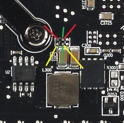
OK. A picture:

measure spots.jpg

First measure the resistance between the two multimeter probes (touch the tips together) with the multimeter set to the lowest ohms (usually 200), this is important. Write that number down.
Measure between the two points indicated by the red lines, then between yellow, then between green.
If you're lucky, the red and yellow pairs will have the same amount of resistance that just the probes had.
If not, write down all those numbers (if you have to adjust the multimeter setting to get a reading, that's fine), and we'll go from there.
 
Ok, measure them all. There were no number on the multimeter. This is how I had it set:

RUzJUtv.jpg

2000 also didn't register anything.

I measured these two:

Y9whh6W.jpg

And they registered 333 with multimeter set to 2000.
 
The little ones are what we're after. These spots:
measure spots.jpg

The big brown things are 16 volt capacitors, that's simple enough. The little things are resistors and could be anything from 0 ohms to a couple million ohms.
It's a big range to guess in :D
 
I had measured all 3 color combinations that you pointed out in the first pic with MM set to both 200 and 2000, should I try again with higher settings on the MM? At 200 and 2000 it just displayed "1". (Same as when tips aren't touching anything)

Edit: BTW, what are your thoughts about the chipped corner of the SMD pointed by the arrow?

EgQbQzB.jpg
 
Last edited:
Yeah, keep going up till you get a reading. That's hugely promising, but we might luck out.

The chipped bit isn't a problem, it's not a large enough chip to change the inductance of the thing (it's an inductor, as a sidenote) much.
 
Worse than me on getting his ".02" in... impressive. I stick to what I know though. :p

Waits for inevitable (death and taxes) reply............... :rofl:
 
Worse than me on getting his ".02" in... impressive. I stick to what I know though. :p

Waits for inevitable (death and taxes) reply............... :rofl:

This sums up EarthDog's quote:
state-farm-dollar-tease-o.gif


@ATMINSIDE
Now I'm lost....

Nvm, I'll just leave (before the mods kick me out)while I can.
 
Are those resistors unmarked on the working card?
The markings would tell exactly what you want.
 
Are those resistors unmarked on the working card?
The markings would tell exactly what you want.

As far as I can tell, the only markings would be "C301" and "C302" silk screened on the PCB in white beside them. Probably not what you're talking about.
 
Back