• Welcome to Overclockers Forums! Join us to reply in threads, receive reduced ads, and to customize your site experience!

Fan Controller / PWM Booster / Regulator / Converter / Etc. Thread!

Overclockers is supported by our readers. When you click a link to make a purchase, we may earn a commission. Learn More.
Bonus post!
The linked connectors are all I've managed to find too. Their tabs are too wide, the proper headers have a thinner tab that is offset to one side.

Unrelated: Is there anything that anybody would like me to make? I'm thinking that a LED controller of some sort might be fun.

*cough* 3pin PWM controller *cough* ;)
No rush, just saying.

I have to mine some more BTC first anyway, just spent most of it :-/
 
What would you like to see in a 3pin fan controller?
When you say 3pin PWM, what exactly are you after?
 
Like these but control 3-pin fans.

Of course, this means controlling the voltage right?
Which could get pricey too I guess eh?
 
there are 3pin controllers out there....

i know we could go back and fourth on this but if one is made. i always say it should be with the reo on the gnd vs the voltage line. you get much better control of the fan with the reo on the gnd vs voltage line.
 
3pin would be voltage control, yeah.
For low power fans, a rheostat is fine. For slightly higher power, a BJT and a pot.
For serious fans it's buck regulator or forget it.

The reason I ask what you're after is that there are plenty of 3pin fan controllers out there that might fit the bill. If they do, they'll most likely cost less.

Now if there are features you want that aren't found on other controllers, that I need to know about :D
Be it small size, a specific shape, especially high power, whatever.

:facepalm:
Didn't even think to look.

Now here's something: My fans run at 12VDC @ 0.4 Amps = ~1500 RPM.
Anyway to make 'em even faster without killing them?

That means giving them more than 12 volts, but how many volts would be too much?
Is that even possible? :shrug:
 
well fans have electric motors just really small, you would need to change the motor. as for electric motors voltage = rpm speed, current = torque, in this case torque might/could be related to static pressure of a fan. though the number of blades and design are a factor.
 
well fans have electric motors just really small, you would need to change the motor. as for electric motors voltage = rpm speed, current = torque, in this case torque might/could be related to static pressure of a fan. though the number of blades and design are a factor.

Sure but what would happen if I fed them say 14 volts?

Would that not speed them up too?
 
They would speed up, it's been done. People used to use the now-removed - 5v rail as "ground" to make 17v. Fans spin fast, then overheat and die at that voltage. They're typically rated to 13.2v though, so you could get a little more out of them with a dc-dc boost regulator. Probably not much though.
 
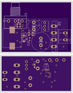
AC input 3pin fan controller anybody?

It'll take ~10VAC to ~20VAC input and make a 5VDC to 12VDC output at a 3pin fan header.
It'll just as happily take a ~13VDC to ~30VDC input and make that same output. In case you want to run computer fans in your car or something I guess.


pcb renders.png

Not completely done, but it'll look something like that if/when I cause it to physically exist.
 
Controlling AC fans is a very different operation. Typically (not always, but usually) you have to vary the frequency of the AC sine wave. It's certainly doable, but it's a lot more complicated.

Most AC fans are 120v or 240v, which is something I'm not touching with anybodies pole, not for sale anyway. Too easy to kill yourself or your user :D

The AC input option is for easy use with a transformer on a wall plug, and to be more specific it's because Sandrat wants it that way.
I may put solder jumpers on it for dedicated DC use, so as to not lose the efficiency going through the rectifier. Not sure if there's enough of a market for it to make it worthwhile.


Tested a quick design.
It did not even sort of work at all. So much for that.
 
Last edited:
AC input 3pin fan controller anybody?

It'll take ~10VAC to ~20VAC input and make a 5VDC to 12VDC output at a 3pin fan header.
It'll just as happily take a ~13VDC to ~30VDC input and make that same output. In case you want to run computer fans in your car or something I guess.


View attachment 143643

Not completely done, but it'll look something like that if/when I cause it to physically exist.

I just noticed you have 2 C1's silk screened on that board :) 1 on top side and 1 on bottom side.
 
The bottom side one is IC1, the I is on the pins so it's hard to see (the fab doesn't print silkscreen on bare copper, it just skips it).
I should probably move it before I send them in though.
 
There's no real point in using small AC fans. An AC motor run direct off the mains (60Hz) can only do 3600RPM while BLDC easily does a lot more than that. Not to mention that small induction motors have horrible efficiency.

Now if you had a large AC fan (e.g. in a HVAC system) or other AC motor that you wanted to control, you can do that quite easily with a VFD.
 
I want to make a VFD just to have made a VFD, not so much for a practical reason :D

EDIT: Though making a VFD juicy enough to run a standard household box fan and cranking the frequency up might be entertaining. Literally overclock a fan!
 
I'm actually working on hacking (more like rebuilding) a 2000W Harbor Freight inverter into a battery operated VFD. However, I'm aiming more for "underclocking" motors.

Back in the days (25 years ago or so), some inverter manufacturer (Tripp-Lite?) had an interesting feature on their high end inverters where you could flick a switch to drop the output voltage and frequency (to something like 100V/50Hz) and thereby get more runtime from the batteries, albeit it only works on resistive and motor loads, not electronics. Nowadays, high end Samlex inverters have something similar, but for a very simple feature, they sure charge an awful lot!
 
Interesting, I like the concept.
I've only worked with inverters as high power (5HP to 15HP) three phase 440v spindle drives on CNC routers. No worries on power consumption there, though lots of speed (hence, voltage and frequency) control. We didn't crack them open (other than to wire them into machine and controller), if/when they went BANG we replaced 'em with new units.
 
I'm actually working on hacking (more like rebuilding) a 2000W Harbor Freight inverter into a battery operated VFD. However, I'm aiming more for "underclocking" motors.

Back in the days (25 years ago or so), some inverter manufacturer (Tripp-Lite?) had an interesting feature on their high end inverters where you could flick a switch to drop the output voltage and frequency (to something like 100V/50Hz) and thereby get more runtime from the batteries, albeit it only works on resistive and motor loads, not electronics. Nowadays, high end Samlex inverters have something similar, but for a very simple feature, they sure charge an awful lot!


WOW I thought my (now blown up) 1750 watt inverter was huge...
 
Back