http://hvacwebtech.com/marksM2.htm < Link to details of TXVs.
Green yes, it is the extra piping that you see, they could be doing some thing ells but at that capacity I think it would be safe to say it is indeed a cooler for the oil.
Phase system is the only approach, LN2 is not an option, try thinking about suggestions and feasibility, That recommendation is dangerous in that sort of setting, it could even deplete the oxygen levels in a room fairy fast if the vent system isn't up to par for that type of usage of the space.
The over all surface of the table MUST be fully insulated along with the bottom and sides, then the holes cut for the base of the artwork this will reduce loade.
at 2.5 Tons nominal cappacity and 2Tons Viable Opperating that will most likely have close to a pound of R-22 in it or so, so you'll definately have to have it emptied by a certified tech, then do the work and have it commissioned to be legal and safe.
Now what I'd do, is get a table that has a wooden deck, get a router and mill out the best patern for the piping on the wooden deck and then put in 3/8 for the evap with neropren foam under the pipe, so that 3 to 5mm of the pipe is above the cut in grooves, then bolt on some aluminium sheeting over the deck, then secure blue cyanofoam on top and bottom along with the sides with the two ends of the pipe sticking out 2 feet.
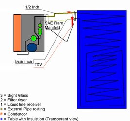
With the plant I would clean it up and get it emptied and pressure tested, Now if it was using a capillery tube, I would remove that, add a receiver that had a 2pound capacity (Basicly it should hold a 120% of the total systems charge) then after the reciver a filter dryer, and sight glass; For the Vacuum side I would add a 1/2" SAE Flare connecter this will be brazed on and secured to the frame of the Condencere plant and after the sight glass a 3/8" SAE flare connecter should be brazed on then secured to the frame of the condencer plant.
Now, with the 2feet of 3/8 pipe sticking out; Place the condencing plant (The A/C with out the evap) in a conveniant spot under or around the table where it will live and opperate; Start messuring how the tubing must be routed, make any needed bends, now cut off any access piping, now Braze on a 3/8 to 1/2 Inch converters and add 5" of 1/2 tubing, this is how the TXV and suction line will be connected; Put on a 1/2" SAE Flare Nut and then flare it (You'll have to probably get a proffesional to do the flaring as it is tricky) and on the other one add 3" of 1/2" pipe and braze on a 1/2" SAE flare and secure to the table.
Now at this point the the table and condencing plant will be totaly seperate; The condencing plant will have two connections, 1: 3/8th" male SAE Flare, and 1: 1/2" male SAE Flare. The Table will have 1: 1/2" Female SAE Flare and 1; 1/2" male SAE Flare.
The TXV will go onto the 1/2" Female flare and will connect to the 3/8th" Flare on the Condencing plant; And between the table and the condencing plant you will bolt on a 1/2" diameter peice of pipe for the suction.
This will make the unit portable to a degree, as in you'll be able to break it up and move it, how ever you'll have to get a tech to recover the refrigerant and vacuum it each time to charge it once re-assembled.
I will add in a MS paint later.