• Welcome to Overclockers Forums! Join us to reply in threads, receive reduced ads, and to customize your site experience!

Sunday Afternoon Modding (How To Put Old Heatsinks To Good Use)

Overclockers is supported by our readers. When you click a link to make a purchase, we may earn a commission. Learn More.

Kojiki

Registered
Joined
Jan 31, 2010
Location
Virginia,usa
Sup OC land, was a little board so i thought i would post up this small heatsink chop shop project for fun. i trimed up some old heatsinks from my gigabyte mobos NB sink and an old dinosaur AMD K6 mobo. and turned them into my new Mosfet coolers. the plus side is i saved $36.00 by doing this the down side is i almost sliced my thumb open twice from the sharpness of the gigabyte NB sink but what do u expect when u saw them by hand with no vice to lock them down lol anyways without further adue.

in the pic u can see i replaced the NB sink with a nice blue zalman sink so now the NB stays nice and cool when i OC whereas before it would of burned your finger with the stock NB sink when OCing.

Now the Only thing left burning body parts is the Mosfests on the left side of the CPU heatsink. wich these new chop shopped peaces should fix when i order some artic silver thermal adhesive. yes i know cable management isnt the best but i dont care mutch atm as im waiting for my new sapphire HD5850 Toxic to arrive before i clean up the case wiring. :)


**update: 2/23/2010 still waiting for thermal adhesive to arrive by ups. im thinking of using the lighter weight larger aluminum heatsinks as they have a larger surface area and should dissapte heat faster, they will get a cooling bonus from the zalman 9900A exhaust as it exits thrue the rear of the case. i should be left with a few 'mm of height clearnace will update soon with more pics and temps. **
 

Attachments

  • 1 [640x480].jpg
    1 [640x480].jpg
    61.8 KB · Views: 2,159
  • 2 [640x480].jpg
    2 [640x480].jpg
    67.6 KB · Views: 2,140
  • 3 [640x480].jpg
    3 [640x480].jpg
    70.1 KB · Views: 2,140
  • 4 [640x480].jpg
    4 [640x480].jpg
    94.8 KB · Views: 2,184
Last edited:
That's pretty cool idea. Keep us updated throughout the install with pics, and don't forget to post final results. Looking forward to seeing how it goes.
 
Results Post

****Sorry it took so long to get the final post out, but here it is****
Note: "All these results were obtained on budget board from gigabyte the MA770-UD3 rev 1.0 bios ver F9D".


i went with the 2 large aluminum sinks i cut in the previous post and boy was that a good choice i attached them last night with the Artic silver thermal adhesive had to give them a 6 hr cure time at room temp, woke up this morning and they settled fine, rock solid contact with a nice thick layer of T.I.M/Epoxy mixture.

at that point i slapped the system back together, unfortunately i did have to remove the mobo due to the large nature of the zalman 9900 Beast.

booted up no problems, restarted the rig went into the bios and immediately proceeded to shatter my 250FSB limit i kept hitting before i modded the mobo with sinks and pushed it to a nice 265FSB

poped multi back to 14X
raised cpu volt to 1.425
rasied NB volt to 1.325
set mem volt to 2.050

restarted, boot up went without flaws, loaded OCCT for a quick 10min stress to let me know right off the bat weather the system was stable, it passed the stress test and the system also passed maxed out setting in Uniengine Heaven Benchmark. during the stress test i opened the side panel on my case and proceeded to manually check all the hot spots and they were all *BARELY* warm to the touch thats nuts since i pushed the volts higher than ever before and the new sinks on the mosfets were pratically cool to the touch where as before they would burn the tips of your fingers off.

So the Mosfet mod was a success in every way possible :rock:
and with that being said i can defiantly feel comfortable in recommending others to do the same mod if their in my same shoes. so case in point take care of your mosfets because they will ruin your OC hopes and dreams if they get to hot :p

<<<<without further delay here are the goods>>>>
 

Attachments

  • Bare Mosfets [640x480].jpg
    Bare Mosfets [640x480].jpg
    99.4 KB · Views: 2,057
  • 2nd Case view [640x480].jpg
    2nd Case view [640x480].jpg
    74.6 KB · Views: 2,060
  • 3rd Case View [640x480].jpg
    3rd Case View [640x480].jpg
    90.7 KB · Views: 2,033
  • Bottom sink view [640x480].jpg
    Bottom sink view [640x480].jpg
    61.4 KB · Views: 2,037
  • Sink Case VIew FInal Install [640x480].jpg
    Sink Case VIew FInal Install [640x480].jpg
    92.8 KB · Views: 2,049
OC results

My OC results After Cooling mod and some pics of an experimental Phenom 2 stock heatsink Mod or is it Massacre???.....
 

Attachments

  • Final OC results 3.7GHZ.jpg
    Final OC results 3.7GHZ.jpg
    256.2 KB · Views: 2,040
  • P2 Sink Before Butchering [640x480].jpg
    P2 Sink Before Butchering [640x480].jpg
    77 KB · Views: 2,016
  • P2 Sink CHopped up 1 [640x480].jpg
    P2 Sink CHopped up 1 [640x480].jpg
    81.6 KB · Views: 2,017
  • P2 Sink CHopped up 2 [640x480].jpg
    P2 Sink CHopped up 2 [640x480].jpg
    84.7 KB · Views: 2,051
  • Polished P2 Sink [640x480].jpg
    Polished P2 Sink [640x480].jpg
    63.3 KB · Views: 1,999
I'm trying to picture your picture. Your heatsink you made thats mounted below the CPU cooler is sitting on the choke coils or the mosfets? The choke coils are the R50 tall square ones and the mosfets are the small flat ones with three solder pins. The mosfets are the ones that get really hot.

So, is the HS where it needs to be or is it just my eyes seeing it wrong?

pic link

http://www.hardwaresecrets.com/fullimage.php?image=12426
 
Last edited:
i see the point your trying to make but the picture u linked is of a motherboard of a completely different design and layout it uses older components. on the MA770-UD3 it has 5, R50 black squares that regulate the power my motherboard is a 4+1 phase before the mod it was only those R50 Black cubes on the mobo that were blisteringly hot to the touch not any other chips around them were hot. so i did succeed in cooling the necessary components :) so no worries their.
 
Okay. If you think so. This is the full article. The mosfets on his board are just like yours, even the middle pin is terminated.

http://www.hardwaresecrets.com/article/616/1

I have a top end modern mobo. The chokes are not cooled, but the mosfets are. You can see it in the pic.

http://www.gigabyte.us/Products/Motherboard/Products_Overview.aspx?ProductID=2960

In this massive uber modern Mobo watercooled block, the Chokes aren't cooled.

http://www.xtremesystems.org/forums/showthread.php?t=245983

My board power circuits looks just like the one in the article when nekkid. At least the basic components, not the layout.

Your stuff.
 
hmm i just noticed i mixed my componetry terminology up it happens....

my cooling experiment wasn't for the mosfets it was for the chokes i dont know why i kept using the word mosfet so much lol sorry guys didnt mean to inadvertently stir up frustrations. but yes the mosfets were never the over heating problem on this board it was the chokes or the Black cubes labeled R50 in the pic above.
so far the system has been running non stop this morning with that overclock pictured above and i removed the side panel again and did a feel test and the mosfets are bairly warm but i can feel where all the heat IScoming from and its the chokes but all that heat the chokes are generating is very effectivly being absorbed by those custom aluminum heat sinks i attached last night. their no longer burning fingers eh. i think in all the temp monitoring softwares i used the one temp that kept registering 80c is now down to 31C. made me wonder if their was a temp sensor on the mobo next to the chokes that kept registering its temp.
only way a temp could be that high cause it wasnt the cpu or any other part of the chipset.

but anyways this was just a fun project i wanted to share with the community so no need to get worked up over it.....
 
Just didn't want you to fry the board, thats all. Otherwise I would of said, "Thats pretty neat". You load on the mosfets mustn't be that bad, odd the chokes would get so hot.
 
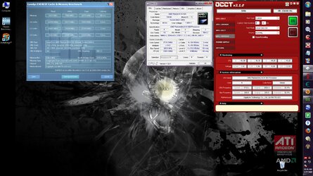
lol your tellin me i thought it was really weird myself but the chokes seem to get so hot that they would give u a really good burn when i pushed 1.4v or more thrue the cpu i couldnt even crack anything above 3.4GHZ without blue screens, so logically i guess the chokes got so hot the power was just completly unstable coming out to the system. but as soon as i slapped those sinks on i easily hit 3.7 GHZ with 1.4vcore.

Worst case scenario if the board for some reason does die on me i can always get a better one or the same board from newegg.com for $55.99 open box lol.
i wont loose sleep over it. wish i had some sort of infrared heat sensor to pickup some surface temps that would be pretty neat.

i think i might cut down that phenom 2 heatsink some more and place kinda like a copper bar over the mosfets iuno was giving it some thought thoe it seems in order for a mosfet to go pop it has to be under some major voltage and 100% system load for a little while without a heatsink on em. if i do add anymore metal to this mobo ill update again with changes and pics for your viewing pleasure :)
 
Inductors get pretty hot actually. Here's where bing showed how important it might be to keep them cool.

Hope you don't mind, some quick & dirty merging job for better comparison view ! :D

For toroid shape inductor like this, it is almost impossible to cool it, while for box shape like recent model, still possible by precision work with small sink.

Even it is difficult to cool the inductor, IMO it is still better to blow those area to improve the cap's life and overall PWM performance.

attachment.php

Credit Link
 
Sorry for bringing up the thread again, but wow!... this is EXACTLY the info I was looking for. Thanks Kojiki for bringing it up. I have a Gigabyte, GA-MA785GM-US2H that seriously heats up the ferrite chokes too. This model also has a 4+1 phase power regulator and with no heatsinks, and it's the chokes that get extremely (burns to the touch) hot. The mosfets stay nice and cool.

I thought it was just me but I couldn't bring up any google hits on chokes getting hot. I wasn't too worried for the chokes themselves 'cos they're pretty bulletproof up to like 1000 degrees, but I was worried about them heating up the components around them. Was even wondering whether there was a heat/ir scan of those components available, and lo and behold, Jason posts one up adding a little more proof. I was trying to figure out whether it was worth putting heatsinks on the chokes and/or the vrms, and this verifies that the chokes could use the help in cooling.

:rock:
 
Add me to the list of Gigabyte owners who experience very hot choke coils. The R50 cubes around the VRM area of my MA785GPMT-UD2H get very hot, but the mosfets themselves seem to stay cool.

I just ordered some of these

http://www.newegg.com/Product/Product.aspx?Item=N82E16835708012

and these

http://www.newegg.com/Product/Product.aspx?Item=N82E16835708011

which should be here tomorrow. The large ones are for the R50s and the small ones will go on the FETs. I'll clean them all up with a little Arctic Silver purifying fluid before I install them. I don't know how much extra overclocking room they'll give me as I haven't yet tried to find my max HCC frequency, but the additional cooling will give me some peace of mind.
 
Back