• Welcome to Overclockers Forums! Join us to reply in threads, receive reduced ads, and to customize your site experience!

Changing crystals on modern motherboards, can it be done?

Overclockers is supported by our readers. When you click a link to make a purchase, we may earn a commission. Learn More.

Veraxis

Registered
Joined
Dec 12, 2015
Location
North Carolina, USA
Hello all,

I was recently given back an older machine that I had rescued and repaired (translation: salvaged from a tech dump and patched up, specs below) as a spare machine for my parents' living room a couple years back. They said that it had become too slow for them, and that I could do either of two things with it: scrap it, or make it faster somehow. According to them, they don't really care one way or the other, so this machine is to be considered 100% expendable in any efforts to make it faster.

I started by doing the obvious: changing out the old HDD for a small SSD I had lying around. The machine is really only used for internet browsing and watching movies, so the decrease in size should not be an issue. The old HDD seemed to be unusually grindy/noisy as well, so I suspect that it was probably on its last legs anyway. This resulted in a pretty significant boost to performance, but I want to go further.

Having finished that, the old core 2 processor and DDR2 RAM in this machine are my next point of concern. Basically, I want to see if I can overlclock them somehow, but that isn't going to be straightforward using the stock Dell Mobo and BIOS. Unfortunately, these old Dell prebuilts have an alternate-side mounting for the motherboard and a non-standard cooler mounting arrangement, and I don't feel like getting a new 775 socket motherboard, new case, and new cooler just for this project. My idea was this: change out the reference crystal on the motherboard and see if I could overclock it the old-fashioned way.

Unfortunately, my initial tests have not been successful so far.

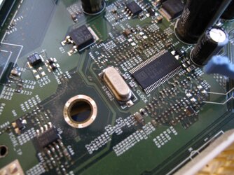
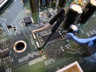
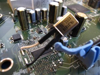
I was able to locate the 14.318 MHz reference crystal and unsoldered it with no difficulties. I then tacked down a pair of leads so that I could easily swap out the crystals as needed for my experiments (see image). sticking in another 14.318 MHz crystal as a control test was sucessful: the machine still boots up and runs as normal, and I was even able to run P95 without any problems. However, any attempts to change the crystal to a value other than 14.318 MHz results in the machine hanging at the BIOS. I have tried 12MHz and 16MHz crystals so far (2.01GHz and 2.68GHz final CPU clock, repsecitively), and both have proven unstable even though 12MHz is technically lower than the stock value. Unfortunately, crystals like this are generally only available in a handful of standard frequencies, and even small changes to the base frequency will result in big jumps in the final CPU clock, so these are my options for crystal frequencies to try in this range (short of putting in values even farther out like 10MHz or 20MHz).

My question is this: is it even possible to overlclock modern machines in this way? so far, my experiments seem to indicate no, but would anyone know of any way to make this stable? maybe I'm doing something wrong? This machine should probably be able to handle some mild overclocking (the stock Dell cooler actually doesn't seem terrible and should be able to handle the heat, the VRMs I'm not too sure). The junk PSU may be an issue as well, but that would not account for the failure when underclocked at a 12MHZ reference.

Specs:

CPU: Intel Core 2 E6600 @2.4GHz
MOBO: MODIFIED Dell Optiplex 745 Mobo
Cooler: Dell 745 stock cooler (6 heatpipe w/ 140mm fan)
GPU: ATI Radeon X1300/X1550 (?)
PSU: stock Dell 300W PSU
RAM: 4x2GB DDR2 800MHz
SSD: 120GB PNY CS1211 (was previously 500GB Seagate HDD)
Case: Stock Dell optiplex 745 case
OS: Windows 7

phpnniAMMPM.jpg

phpfiJtYqPM.jpg

phpwsDCIOPM.jpg
 
I don't think you can OC that way on a new system.
That crystal is probity not even for the cpu
 
Well, that's why I'm here asking about it. Correct me if I am wrong, but my basic understanding is that a modern motherboard bus is controlled by a reference frequency that is multiplied using a phase-locked-loop (PLL) up to a 100MHz bus frequency (200MHz for AMD), and that 14.318 times 7 approximately equals 100MHz, so changing that base frequency should (in theory) allow the system to be overclocked at the hardware level. There is very little reference material that I could find on overclocking modern systems this way, which is exactly why I was curious about trying it. :)

If you do not think that is the right crystal, then which one is? There are a few other crystals on the board (for example, there is also a 25MHz cystal that I am fairly certain from researching online is used as the reference clock for the ethernet communations port). Also, the crystal is physcally located just next to the CPU socket, so everything I have seen so far points to that crystal as being the bus reference clock.
 
I am not sure of this series of processor, but the PLL is either built into the chip or will be a separate chip. You will have to follow/buzz out the traces on the crystal. If they go directly to the CPU, then the PLL is built into the CPU. I think it runs into a separate PLL chip.

Next, all PLLs have a "lock" range on them for the input frequency (i.e. the reference crystal). Based upon where the crystal goes (the CPU or another chip), you can look up the input frequency lock range from the chip datasheet. This will give you the range of values.

The bigger problem you may run into...I am pretty sure that the PCI and memory bus frequencies are derived from this crystal. So, if you go too far off (either low or high), the PCI bus will hang.

Another way to get different frequencies, is to use a higher frequency clock and run through a frequency divider circuit (like a flip flop). This will require much more "modification" to the board. Add to that, the device is 2 pins...so it's a crystal...not a 4 pin like a crystal oscillator clock chip.

(Nice solder job by the way!)
 
Last edited:
Here's a pretty good article about "tuning" the frequency of a crystal:

http://www.statek.com/pdf/tn33.pdf

That was an interesting read. AFAIK, 18-20pF is pretty much the de-facto standard for most discrete crystals, but definitely something to keep in mind. capacitive trimming is a pretty common technique for fine-tuning crystal oscillators, but in my experience, it is typically only used to adjust the frequency by small amounts one way or the other. If I want to overclock this in a way that will produce a meaningful performance increase, it will likely be necessary to make fairly large changes. Unfortunately, I do not know the load capacitance of most of the random crystals in my junk box, but I have enough electrical knowledge that I might be able to measure the impedances if necessary.

I think you are correct that I need to research where and how the clock is generated for these Core 2 chips, and what the safe ranges are for messing with the frequencies. Clearly my reckless approach of just picking a crystal and swapping it isn't going to work :-/. I agree that there is a real issue in that overclocking by this method is going to overclock practically everything across the board, including the PCI bus and other parts not really intended to be messed with like this. Finding out where the signal paths are will probably involve doing a bit of research and a lot of staring intently at the traces on my mobo...

The other major unknown for me is how the software layer is going to handle this. by manually modifying the hardware, the OS and other software will be overclocked but still "think" the system is still running at the stock frequency, which may cause timing errors which could crash the OS regardless of whether the hardware is able to handle it.

I'll keep everyone posted. if anyone has any additional thoughts, I would be happy to hear them. Clearly this is a far more involved and unusual method of trying to overclock than I had hoped, but it will still be interesting to see if it can be done (or at least determine definitively that it cannot be done so that future overclockers don't have to spend time on this). I suppose to some extent it says something about me that I would sooner take a soldering iron to my motherboard than try and crack into the motherboard's bios to do this :p.
 
Here's something: I took a quick search around the board and was able to locate the central clock generator chip: a chip with the part number 9LP505-2HGLF made by IDT (actually, you can clearly see the chip right next to the reference crystal in my photos from earlier). For some reason, I am unable to locate a datasheet for this exact part, but was able to find datasheets for two of its close relatives: 9LP505-1 and 9LP525-2. Judging from these datasheets, the pinouts are quite similar, so with some additional searching on the board, I may be able to piece together where the inputs for my chip are based on the other datasheets. These datasheets confirm our suspicions about mass overclocking of the board-- this chip seems to be the reference controller for practically every part of the board from the PCI bus down to the USB clock, so changing the reference crystal is likely wreaking havoc all over the place. :shock:

I'm still reading through the datasheets to figure out exactly what makes these things tick (literally), but there may be some hope here after all: my initial reading seems to suggest that the CPU base clock can be manually selected using certain input pins. This would allow me to overclock the CPU directly without messing up the rest of the board with it. I'm probably gonna sit down for a few hours tomorrow and just read these datasheets so I can devise a plan of action before I set about to mutilating my board again. I'm definitely intrigued, though. :sly:
 

Attachments

  • IDT_9LP505-1_DST_20150709.pdf
    196.6 KB · Views: 208
  • IDT_9LP525-2_DST_20101108.pdf
    226.8 KB · Views: 192
Have you considered checking to see if your board supports 45nm CPUs (might require a BIOS update). A 1066 to 1333 BSEL pad-mod would be a lot easier to do and it has been documented to work.

http://www.overclockers.com/forums/showthread.php/658847-Intel-LGA775-Pad-Modding

Wow, I was not aware of this method! Actually, the three BSEL 0, 1, and 2 frequency selection pads on the chip seem very similar to three of the inputs on the clock generator chip called FSL A, B, and C, So I wonder if the two might actually be directly connected to one another. On the clock generator, many of these pins can be configured as either inputs or outputs, so it may be safer to perform the modifications on the chip side.

Further reading of the datasheets also suggests that it may be possible to reprogram the frequency selection registers via the SMB, but that would require determining the device address of the clock generator chip and then injecting control signals onto the lines either by way of the SMB controller somehow or through an external microcontroller. I actually have some small experience with sending these types of register control signals to Fractional-N synthesizers for RF applications, but those typically use either SPI or three-wire serial communications, and the SMB/I2C standard is all around a much more tedious and complex communications protocol to work with.
 
I need to start a thread for ideas like this so I can filter out bad ideas before you start doing something. Next to the Mosfet replacement thread, this one is better.

You CANNOT replace the crystal, unless it is an exact copy of the last one. You WILL NOT improve any part of your system by trying to up the ref clk. This literally has nothing to do with overclocking, or the frequency in the CPU. What you have replaced, is the reference clk to the PLL, but this is not the PLL to the CPU. That PLL is in the CPU, and you have full access to it via the BIOS. This particular PLL is for the BCLK of the CPU. The BCLK PLL is highly tuned, and designed by Intel with the help of Dell engineers. This clk system is a no touch zone. Your CPU will never bootup because the PLL will not be able to create a lock on the loop to spit out the 100MHz bus to the CPU.

Here is what you have actually done: Lowered the performance of the system as a whole. Crystals are very special, especially when they are used with super fast systems like CPUs, Antennas, and transmission lines. There are specific ratings, such as PPM, that are used to categorize crystal so that engineers can pick the most suitable part for the design. The traces from the crystal, and those around the PLL were calculated and ran through simulations to make sure that there would be no added signal noise, or loss of signal quality. The small amount of soldering and leads you have applied, has increased inductance, added unnecessary capacitance, and most likely offset the slew and timing of the input to the PLL. In short terms, you have added a lot of jitter and impedance.

The only way to increase the performance of this box is to do the pad modding, or to find someone to make you a BIOS for that system. I would say there is one out there in existence. There are some old BIOS programmers hanging around XS forums.

edit*

OP, to your last post, no don't.
 
Last edited:
I need to start a thread for ideas like this so I can filter out bad ideas before you start doing something. Next to the Mosfet replacement thread, this one is better.

At least I can take consolation in knowing that this is only the second dumbest idea that Dolk has heard. :D

In all seriousness, though, I think we can safely say that my initial attempt was a real botch job, plain and simple. Hopefully, at least, my embarrassment might serve as a warning to any others who find this thread. I pretty much knew going into this that there was only a slim chance of any of this nonsense producing a workable result, and there is a reason why I decided to do this on a junk PC that I would not care about losing. My real goal here was to get a clear answer as to whether this was something that could be done, and if not, determine precisely why not. I think your explanation gives a satisfactory answer as to why it cannot be done in this manner.

My main issue was that, prior to this, I was not able to find much in the way of discussion on this subject, and I would not have felt the need to embark on this insane experiment had I been able to find a thread anywhere that gave sufficient explanation as to how the PLLs in modern systems worked and why this idea was now obviously doomed to fail.

Honesty, I have no real desire to go messing with the SMB to control the clock generator, so no worries there. The previously mentioned pad modding seems like the most proven and stable option, so that is probably what I am going to pursue.
 
I'm kinda surprised no one brought this up, but changing crystals to overclock hasn't been done since the 486 days, as starting with the Pentium, it was no longer possible to do so (afaik, it never worked when attempted).
 
Alright so there is something to really discuss here, and that is searching for information to projects like this. So lets say you want to modify a design on a motherboard, well the first thing is the reason why. Don't limit your thoughts on, I want to OC my system further. You need to identify an area that seems weak, lacking of something, and you have an idea of what you want to do with it. Simple ideas like increasing the ref clk of a PLL seems rather simple, but in the ECE world you would be laughed at. You will not find any search results for something like this because engineers know that you can't do this. This is simply 100% ignorance with those that have not taken the right classes, or worked in the right industry fields. There is nothing wrong with those that want to learn! I encourage EVERYONE to do something like this so you CAN LEARN! I'm just here to help guide you and laugh, and give something to my co-works to laugh about. :)

Say you do want to update the ref clk of the PLL because you thought it would increase the BCLK of the CPU. Understandable, I see where you were coming from. First thing you should do is look up the parts that you believe control this circuit. Start to piece together a circuit of the system if you don't already have a reference schematic (issued by the manufactures) or already have some history in working with systems like these. Once you start building the picture, you can start to identify weak points. You saw that the ref clk can't be replaced (by experimentation, nothing wrong there), but could be changed by the SMBus. What you didn't know is that the SMBus hooks into the VR SMBus that goes between the CPU, and VR. The CPU will actually tell the ref PLL to lock into the 100MHz (if you changed the ref PLL output clk, you would hurt the CPU. The CPU outputs the BCLK used by everyone not the PLL).

What I am getting at is that you need to do all the research you can, before you touch something. But you can definitely skip all the research and investigate if you are 100% ok with the system dieing unexpectedly and without knowledge to you and why it happened. My understanding and engineering experience was higher than some of my fellows at school because of my OC projects. I also performed things like this when I was younger, because I wanted to learn. Hopefully, I am giving some good advice so that you don't go the same way I did for so long, before realizing that research is more important than just exploring.
 
If you go pad option...be careful with pulling pins high or low. If these pins go to the other chip, you would effectively be creating a short at the other chip. (It tries to drive it high, but you have connected to low...and vice-versa).

You will need to either find a schematic or buzz out the traces. If it's only connected to the CPU and other chip, then you lift the pins on the other chip before making hard high/low connections at the CPU.


Interesting read. Never would have even thought of trying this. Just goes to show you the different levels of people's understanding of computers. My friends think I'm pretty savvy, but compared to Dolk I'm a dolt.
 
Another reason for not changing the crystal is that crystals have 2 modes of oration, series and parallel. So if a crystal is cut for series mode at say 20MHZ is put in a oscillator circuit running in parallel mode, it will not put out 20MHZ. So if you have 2 crystals of 14.31818 MHZ, and 1 is made for series mode and 1 for parallel mode, they will not put out that frequency if put in the wrong circuit.
 
Back