-
Welcome to Overclockers Forums! Join us to reply in threads, receive reduced ads, and to customize your site experience!
You are using an out of date browser. It may not display this or other websites correctly.
You should upgrade or use an alternative browser.
You should upgrade or use an alternative browser.
Codename XmasList project
- Thread starter SwartHack
- Start date
- Joined
- Apr 3, 2015
- Location
- Planet Earth
- Thread Starter
- #62
Blaylock said:...more appreciation for some of the professional builds out there.
No crud! I can't really imagine going at it from scratch, especially after this process...
Like I said, even for next time I will cut-off the ends of stock cable, to appropriate lengths, then sleeve and re-pin.
You would need a good jig/rig to cut/strip the cables from stock. I was thinking of an old-school paper cutter, like from school days...
Where you'd spool it through, Cutting lengths.
Considering these sleeves I got are machine made and there is still a slight variance,
goodness I could see a total OCD break-down/collapse on my part!!!
(I am going to request a How-Its-Made episode on these pre-sleeve jobs I used.
I love that farcking show!
 Does anyone else like to nap to it? You retain all the information)
Thanks for the props ATM! Will be showcasing this rig in the Cup ASAP. Maybe it will be pinned-down and finished by the end.
Hope to post some decent subs based on the preliminary Bianch testing...
Cheers
- Joined
- Jun 28, 2012
Maybe it will be pinned-down
Pun intended?
- Joined
- Apr 3, 2015
- Location
- Planet Earth
- Thread Starter
- #64
Uh, err, well.. sure!Pun intended?
Actually in this case not really, honestly. If it was intended, I would have been sure to laugh at it myself and point out how funny I am...
I guess the correct term I am really looking for is "all buttoned up".
Prost
- Joined
- Apr 3, 2015
- Location
- Planet Earth
- Thread Starter
- #65
A Slight Repose - Some Tool Talk
I am taking a few days off and not continue obsessing about powering up...
Why?
Well, in review of my work I am not happy with the re-pinning, and I knew this risk going into it.
Because these crimpers are not specifically designed for these mini-fit atx/pcie/eps pins.


I was going to point out a few Tool Tips in the previous post, but never worked it in.
I wanted to mention, to make sure to get both of these tools if you want to conserve sanity.
Yeah, 101 DIY - make your ATX pin removal tool. Go with that and say good-bye to any remaining rational sense, especially if doing a bunch!
Just get these tools. The silver one is indispensable for those tight pins. The black one's tines are a little thicker/beefier.
Really I am not sure what these crimpers are "specifically" designed for.
I have used them with everything I have previously needed to crimp (JST, molex, mini-fit molex, and whatever those pins are on the 3 and 4 pin fan connectors and 2 pin header connectors)
I can and did use these and was able to perform the required crimps, but I had to double crimp, start with big, then finish with small...
And the whole pin tends to get tweaked crooked. It still inserts and locks, but... I don't like it...
Especially when I am looking at pinning this:

I gambled a little and counted on my local "Twilight Zone" electronics store:

to have one, and surprising they didn't.
(This place is incredible! I want to do a video exposé on them sometime. Think 70's counter service, that's accumulated stuff since then, with stuff EVERYWHERE!)
So I ordered one of these and don't get for a few days

And needed to get some more pre-sleeved rigs for the second gCard cables.
So I am going to just chill on it a few days, maybe work on cleaning up the fan wiring since I got that all done.

Notice the SATA power adapter on PWM hub. The front panel assembly also has one, and I believe I will need one or two more eventually...
No SSDs on this rig!
So need to work on a custom SATA cable for these power only requirements
and add one more important step.
FIVE-
Know when to walk away, put the crimper down before you hurt yourself. Just walk away!
Especially when tired, BUT also when frustrated or feelings of, "I have to finish this now",...well..No you don't!
Your just gonna screw something else, throw a wobbler and end up with a screw driver sticking out of the wall again! (nice throw by the way)
Just walk away...
Tots Zien
I am taking a few days off and not continue obsessing about powering up...
Why?
Well, in review of my work I am not happy with the re-pinning, and I knew this risk going into it.
Because these crimpers are not specifically designed for these mini-fit atx/pcie/eps pins.
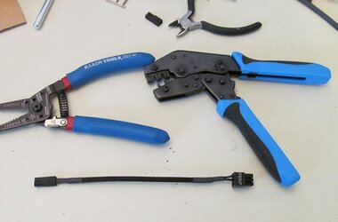
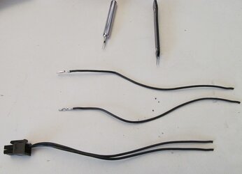
I was going to point out a few Tool Tips in the previous post, but never worked it in.
I wanted to mention, to make sure to get both of these tools if you want to conserve sanity.
Yeah, 101 DIY - make your ATX pin removal tool. Go with that and say good-bye to any remaining rational sense, especially if doing a bunch!
Just get these tools. The silver one is indispensable for those tight pins. The black one's tines are a little thicker/beefier.
Really I am not sure what these crimpers are "specifically" designed for.
I have used them with everything I have previously needed to crimp (JST, molex, mini-fit molex, and whatever those pins are on the 3 and 4 pin fan connectors and 2 pin header connectors)
I can and did use these and was able to perform the required crimps, but I had to double crimp, start with big, then finish with small...
And the whole pin tends to get tweaked crooked. It still inserts and locks, but... I don't like it...
Especially when I am looking at pinning this:
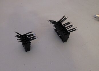
I gambled a little and counted on my local "Twilight Zone" electronics store:

to have one, and surprising they didn't.
(This place is incredible! I want to do a video exposé on them sometime. Think 70's counter service, that's accumulated stuff since then, with stuff EVERYWHERE!)
So I ordered one of these and don't get for a few days

And needed to get some more pre-sleeved rigs for the second gCard cables.
So I am going to just chill on it a few days, maybe work on cleaning up the fan wiring since I got that all done.
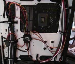
Notice the SATA power adapter on PWM hub. The front panel assembly also has one, and I believe I will need one or two more eventually...
No SSDs on this rig!
So need to work on a custom SATA cable for these power only requirements
and add one more important step.
FIVE-
Know when to walk away, put the crimper down before you hurt yourself. Just walk away!
Especially when tired, BUT also when frustrated or feelings of, "I have to finish this now",...well..No you don't!
Your just gonna screw something else, throw a wobbler and end up with a screw driver sticking out of the wall again! (nice throw by the way)

Just walk away...
Tots Zien
- Joined
- Sep 7, 2013
Crap Swart that sleeving looks real good!! 
Looks good so far though. Wonder how make Km of wires you have in that case so far? 2Km?
Now please dump moar pics on the thread. If my interwebz didn't die (which it didn't) then there isn't enough pictures!
Besides, what's a project log without pictures eh?

Looks good so far though. Wonder how make Km of wires you have in that case so far? 2Km?
Now please dump moar pics on the thread. If my interwebz didn't die (which it didn't) then there isn't enough pictures!
Besides, what's a project log without pictures eh?
- Joined
- Apr 3, 2015
- Location
- Planet Earth
- Thread Starter
- #67
Silver_Pharaoh said:Wonder how much Km of wires you have in that case so far? 2Km?
Huh? What's a Km.
Dunno how much cable so far???
I think about 1.24274 miles..
So here it is. Little fanfare, no trumpets or glorious exultation.
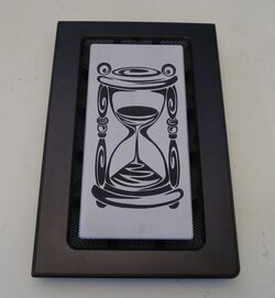
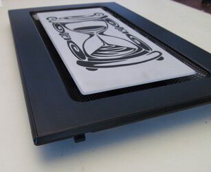
No use in trying to keep under wraps till some grand unveiling,
especially cause its so farcking cool!!!
Started this project about 3 months ago. Its one of a number of graphic/custom mods going into the final build.
I did the 3D model for the CAM and doctored a stock raster image for vector laser etching.
I obviously did not actually do the work. A CAM mill and lasers would be so awesome. Maybe someday.
Luego
- Joined
- Sep 7, 2013
Wow yeah!! That really looks good swart! 

- Joined
- Apr 3, 2015
- Location
- Planet Earth
- Thread Starter
- #71
You'll burn your eye out!!!
So huh hu hu huh huh, lasers. Shiny!
Man never really looked..
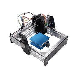
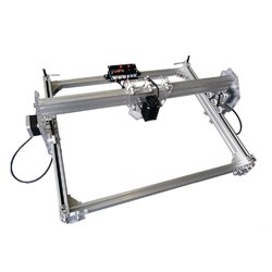
I would love to play with one of these, or similar. I believe most of them you put together and seem to come mostly from world market vendors.
I can't believe how inexpensive they are. I am sure you get what you pay for.
Seems there is a salient DIY community out there for these and 3D printers. There are a ton of these put together kits.
EVERYTHING comes/ships from China!?
These are supposedly cool/cheap because you can move it around on one larger piece. Not sure how that works?
https://www.amazon.com/SUNWIN-Engraving-Machine-Engraver-Printer/dp/B01GR9GHBS

https://www.amazon.com/Desktop-Engraver-Engraving-aluminium-Material/dp/B01EFP5ALO

For big boys:
https://www.amazon.com/CAMFive-CFL-CMA-1080K-cutting-engraving/dp/B00AN9JVEO

Salud
So huh hu hu huh huh, lasers. Shiny!
Man never really looked..
I would love to play with one of these, or similar. I believe most of them you put together and seem to come mostly from world market vendors.
I can't believe how inexpensive they are. I am sure you get what you pay for.
Seems there is a salient DIY community out there for these and 3D printers. There are a ton of these put together kits.
EVERYTHING comes/ships from China!?
These are supposedly cool/cheap because you can move it around on one larger piece. Not sure how that works?
https://www.amazon.com/SUNWIN-Engraving-Machine-Engraver-Printer/dp/B01GR9GHBS
https://www.amazon.com/Desktop-Engraver-Engraving-aluminium-Material/dp/B01EFP5ALO
For big boys:
https://www.amazon.com/CAMFive-CFL-CMA-1080K-cutting-engraving/dp/B00AN9JVEO
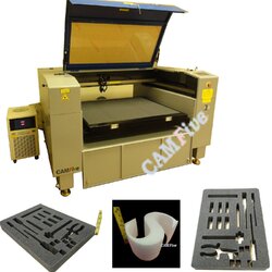
Salud
- Joined
- Apr 3, 2015
- Location
- Planet Earth
- Thread Starter
- #72
Front Panel Door
So no graphic for this yet. Suggestions???
(has audio, turn up your volume)
EDIT:
OK, here is what I have as clip-art of possibilities.
From here we either go "dark" or "family".
I think it needs a dark personality, using demonic overclocking power!!


The concept for the door is reverse contrast. So the piece will be anodized black, and the etching will be silver.
So the type/style of image really matters, where we want the contrast to POP the image. Hence the B&W samples.
But I got a local air-brushing guy who is also going to contribute on the interior, etc.
(Man, I wish had some mad air-brush skills. Decent sketcher, but it ends there. Maybe I can learn something from this guy.)
Still considering extent/style/theme of interior graphic mods. Will post some ideas eventually for consideration.
Eskerrik Asko
So no graphic for this yet. Suggestions???
(has audio, turn up your volume)
EDIT:
OK, here is what I have as clip-art of possibilities.
From here we either go "dark" or "family".
I think it needs a dark personality, using demonic overclocking power!!






The concept for the door is reverse contrast. So the piece will be anodized black, and the etching will be silver.
So the type/style of image really matters, where we want the contrast to POP the image. Hence the B&W samples.
But I got a local air-brushing guy who is also going to contribute on the interior, etc.
(Man, I wish had some mad air-brush skills. Decent sketcher, but it ends there. Maybe I can learn something from this guy.)
Still considering extent/style/theme of interior graphic mods. Will post some ideas eventually for consideration.
Eskerrik Asko
Last edited:
- Joined
- Apr 3, 2015
- Location
- Planet Earth
- Thread Starter
- #73
In the Cup!
So a few things since my last update...
Obviously got distracted with AutoCad, etc...
Also kinda put the cables as a side project for now so I don't rush them.
Plus when I ordered the additional pre-sleeved wires I needed to finish I got:

(Hardy har, so I RMA'd on the web-site, but told them I was keeping the cordage. No charge!)
And, look for an upcoming post on PSU forum regarding another reason I walked away from the cables for a bit.
(The PSU specs and the stock cable are different!!! Do not look too long or try to decipher, it is already outdated.)

Because of the pending question, I figured I better just fire up with the stock cables.

(whoot-whoot-whoot, check out the new 4k rig!!!! I went to BestBuy cause I wanted one "NOW!!!"
I couldn't fire this baby up on some old ratty monitor and had planned on this for some time,
They only had ONE and it just happened to match so cool, I couldn't have planned it better!!!)


So been there for a couple of days, going through the paces and such.
I'll have some AID64 stress reports posted soon, but stock 4000GHz idle cpu temp 20 C, 4800GhZ@4000MHz Dfreq. 30 C idle.
I knew this DDR4 I have has potential, so I started there:

http://hwbot.org/submission/3274378_swarthack_memory_clock_ddr4_sdram_2060.6_mhz/
Will be looking at other stages/subs as we progress here...
Salud
So a few things since my last update...
Obviously got distracted with AutoCad, etc...
Also kinda put the cables as a side project for now so I don't rush them.
Plus when I ordered the additional pre-sleeved wires I needed to finish I got:
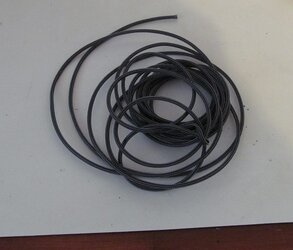
(Hardy har, so I RMA'd on the web-site, but told them I was keeping the cordage. No charge!)
And, look for an upcoming post on PSU forum regarding another reason I walked away from the cables for a bit.
(The PSU specs and the stock cable are different!!! Do not look too long or try to decipher, it is already outdated.)
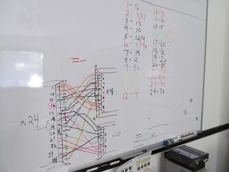
Because of the pending question, I figured I better just fire up with the stock cables.
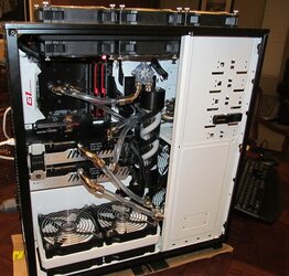
(whoot-whoot-whoot, check out the new 4k rig!!!! I went to BestBuy cause I wanted one "NOW!!!"
I couldn't fire this baby up on some old ratty monitor and had planned on this for some time,
They only had ONE and it just happened to match so cool, I couldn't have planned it better!!!)
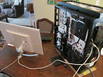
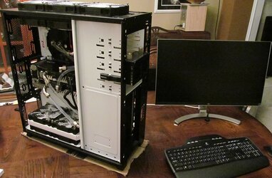
So been there for a couple of days, going through the paces and such.
I'll have some AID64 stress reports posted soon, but stock 4000GHz idle cpu temp 20 C, 4800GhZ@4000MHz Dfreq. 30 C idle.
I knew this DDR4 I have has potential, so I started there:
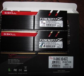
http://hwbot.org/submission/3274378_swarthack_memory_clock_ddr4_sdram_2060.6_mhz/
Will be looking at other stages/subs as we progress here...
Salud
- Joined
- Sep 7, 2013
Sweet Swart!
Looking forward to seeing the reverse anodized front panel.
As for suggestions for it, my mind is blank as it usually is.
Nice sub too! What were the timings for that sub?
Looking forward to seeing the reverse anodized front panel.
As for suggestions for it, my mind is blank as it usually is.

Nice sub too! What were the timings for that sub?
- Joined
- Apr 3, 2015
- Location
- Planet Earth
- Thread Starter
- #76
Silver_Pharaoh said:...What were the timings for that sub?
18-22-22-42 (it shows in the cpu-z verification link)
That's the stock settings for @3866, which I usually run around 16-18-18-38, depending on what I am doing.
Since some feedback on Cup thread, I have lowered my multi to x35, went with one stick and loosened my timing as much as possible. and cranked up DDR volts.
I managed to bump a little, but then things got screwy and I had other things to do...
I was getting 2100 but could not save validation file...
http://hwbot.org/submission/3275086_swarthack_memory_clock_ddr4_sdram_2080.2_mhz1
I think I am on the right track anyway. I haven't tried the other stick yet.
Lochekey said:...really though I stumbled across these two...
..yeah, there are soo many images out there.
Goal is to find one that isn't some stock photo with water-mark. Low res is not a problem as we vectorize the photo anyway.
You can work on shade groupings to eliminate most of water-mark. I totally ripped off the elephant pic for WhiteElephant front panel.
I spent hours cleaning up that photo for engraving. But actually OK, not really illegal, unless I was like manufacturing WhiteElephant rigs and selling them.
In the end it is a totally different format/appearance.
You missed this one!

Buenas!
- Joined
- Apr 3, 2015
- Location
- Planet Earth
- Thread Starter
- #77
Editing graphics for laser etching
I have kinda left out one of my activities is this proj...
At first I was all jacked for the big unveils, but when will that eventually happen?
And by then its all just, "Oh, neat!"
So, in my infinite desire to transcribe my build activities for immortal glory...
I am going to share with you some techniques for working with images for CAM/CNC device input.
https://en.wikipedia.org/wiki/Computer-aided_manufacturing
https://en.wikipedia.org/wiki/Numerical_control
So how does SwartHack do it?
Well first off you really do need a good graphics program.
Adobe can kiss my sister, all they offer is subscription services.
I ended up purchasing an actual copy of Corel Home & Student.
On sale now for 99$!!!!
http://www.coreldraw.com/us/product/home-student/
This will do anything Adobe Illustrator and Photoshop will do.
Caution-If you have never used a Graphics Suite before, the GUI can be overwhelming.
Just go through some of the tutorials. There are tons.
So I create a project in Corel Draw (vector). Not Photo-Paint(raster).
And set the page size to match the target piece.
Then import jpeg and keep actual size.

Problem is that its so small, cause I grab these images from wherever, just right-clicking, save image as...
Luckily, this one has no water marks.
So here is where we edit the bmp object Corel Draw created in Photo-Paint.
You just click the bitmap layer and it opens in Photo-Paint.
Here is where you will re-sample (not re-size) and crop the image to the desired size. Also save the image as grayscale.
Once finished you simply save-quit and return to Draw.
(I have found this is the best way to go about it, instead of trying to edit images first before importing to Draw
This way also preserves the original image)
And now your image looks like:

Now the fun part. Converting the bitmap to vector.
Here we use the Outline Trace tool.
This comprehensive tool has a preview screen where you can apply many different trace routines/settings
All returning different results. The goal here is get the least amount of shade groups with the best detail.
You also remove the background during this process.
After some time playing with filters and smoothing options, I managed to get this...

WHAT! Huzzah, That!??
Well, remember we are doing reverse/relief etching relief and we removed the background,
So what is total white will not get etched, only the shaded areas.
So, when I want to see the end effect, I just turn on a black background:

And SHAZAM!!!

Lets not get to excited!!!
there is a ton of work left to do before this can go to the laser bench.

What I got was 10 different groups of grayscale objects. Curves to be exact.
I labeled each group by its grayscale value. Here I have already combined a 40 and 60 group into one single 60 object.
I need to go through the other groups and see where I can whittle down to maybe 6 shades.
You can also see all the relics, like the dots on the right gate-post. These need to be cleaned up.
Each group has 100's of curve objects that need to be edited/deleted/combined.
You need to get to the same amount of objects as shades, otherwise the laser bench does not work right/well.
This is where time comes in. I'd expect at least 2-3 hours of editing, all zoomed in on tiny pixels to get this ready, just to give to the guy.
This is also where the huge $savings come in, when you can just give somebody a file and its all good to go.
Freaking graphic artisits charge more than programmers these days...
I am not proceeding to that point right now with this image, yet. As far as I am concerned, I have just pre-processed it for a look-see.
I am also not machining the part, as I discovered the cover of the door is actually anodized aluminum (duurrr):

So I am just gonna etch right on that. I am also gonna see if I can get a replacement from Phanteks, so I'll have the stock piece, like the fan cover.
Speaking of fan cover, I went through the same process, but grouping everything into one final all-black layer.
I am gonna give this image a run-through to see how it transforms, but there may be too much detail...

So there you go, some of the curtain pulled back
Ez Horregatik
EDIT: This is cool!

I have kinda left out one of my activities is this proj...
At first I was all jacked for the big unveils, but when will that eventually happen?
And by then its all just, "Oh, neat!"
So, in my infinite desire to transcribe my build activities for immortal glory...
I am going to share with you some techniques for working with images for CAM/CNC device input.
https://en.wikipedia.org/wiki/Computer-aided_manufacturing
https://en.wikipedia.org/wiki/Numerical_control
So how does SwartHack do it?
Well first off you really do need a good graphics program.
Adobe can kiss my sister, all they offer is subscription services.
I ended up purchasing an actual copy of Corel Home & Student.
On sale now for 99$!!!!
http://www.coreldraw.com/us/product/home-student/
This will do anything Adobe Illustrator and Photoshop will do.
Caution-If you have never used a Graphics Suite before, the GUI can be overwhelming.
Just go through some of the tutorials. There are tons.
So I create a project in Corel Draw (vector). Not Photo-Paint(raster).
And set the page size to match the target piece.
Then import jpeg and keep actual size.

Problem is that its so small, cause I grab these images from wherever, just right-clicking, save image as...
Luckily, this one has no water marks.
So here is where we edit the bmp object Corel Draw created in Photo-Paint.
You just click the bitmap layer and it opens in Photo-Paint.
Here is where you will re-sample (not re-size) and crop the image to the desired size. Also save the image as grayscale.
Once finished you simply save-quit and return to Draw.
(I have found this is the best way to go about it, instead of trying to edit images first before importing to Draw
This way also preserves the original image)
And now your image looks like:

Now the fun part. Converting the bitmap to vector.
Here we use the Outline Trace tool.
This comprehensive tool has a preview screen where you can apply many different trace routines/settings
All returning different results. The goal here is get the least amount of shade groups with the best detail.
You also remove the background during this process.
After some time playing with filters and smoothing options, I managed to get this...
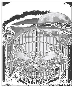
WHAT! Huzzah, That!??
Well, remember we are doing reverse/relief etching relief and we removed the background,
So what is total white will not get etched, only the shaded areas.
So, when I want to see the end effect, I just turn on a black background:
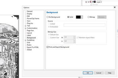
And SHAZAM!!!

Lets not get to excited!!!
there is a ton of work left to do before this can go to the laser bench.
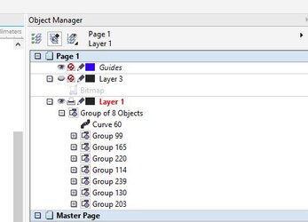
What I got was 10 different groups of grayscale objects. Curves to be exact.
I labeled each group by its grayscale value. Here I have already combined a 40 and 60 group into one single 60 object.
I need to go through the other groups and see where I can whittle down to maybe 6 shades.
You can also see all the relics, like the dots on the right gate-post. These need to be cleaned up.
Each group has 100's of curve objects that need to be edited/deleted/combined.
You need to get to the same amount of objects as shades, otherwise the laser bench does not work right/well.
This is where time comes in. I'd expect at least 2-3 hours of editing, all zoomed in on tiny pixels to get this ready, just to give to the guy.
This is also where the huge $savings come in, when you can just give somebody a file and its all good to go.
Freaking graphic artisits charge more than programmers these days...
I am not proceeding to that point right now with this image, yet. As far as I am concerned, I have just pre-processed it for a look-see.
I am also not machining the part, as I discovered the cover of the door is actually anodized aluminum (duurrr):
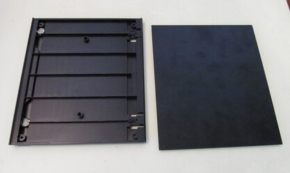
So I am just gonna etch right on that. I am also gonna see if I can get a replacement from Phanteks, so I'll have the stock piece, like the fan cover.
Speaking of fan cover, I went through the same process, but grouping everything into one final all-black layer.
I am gonna give this image a run-through to see how it transforms, but there may be too much detail...

So there you go, some of the curtain pulled back
Ez Horregatik
EDIT: This is cool!
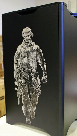
Last edited:
- Joined
- Sep 7, 2013
Seems complex swart, but probably not once you get used to it eh?
Excited to see the results!!!
Excited to see the results!!!

- Joined
- Apr 3, 2015
- Location
- Planet Earth
- Thread Starter
- #80
Quick Word on CAD Development
If you want to dive in the rabbit hole even deeper, and create 3D models...
I have some words of advice for the home enthusiast/hobbyist.
Which means YOU!!
So for the front panel:
http://www.overclockers.com/forums/...List-project?p=7907181&viewfull=1#post7907181
I used FreeCAD:
http://www.freecadweb.org/
FreeCAD is a pretty significant group of significant people that have really put a thorn in AutoDesk's side.
It's total OpenSource and uses Phython to extend/customize the UI.
You don't have to know Python to use FreeCAD.
I'll get it out now, if you want to do 3D modeling....
JUST USE FreeCAD!!!!
And not just for dinky silly stuff like this, but for the entire 3D world, i.e. like your house,
It has soo much help and tutorials, its kinda hard to figure out where to start based on what kind of workbench you are using.
For stuff like this, and machine parts, etc use the Design Workbench...
Check out all the cool applications:
http://www.freecadweb.org/wiki/?title=Screenshots
OOOOooooHHhhaaaa - How bout something like this:

That is cool shiat.
DOn't even think about AutoDesk, mostly cause of the Price and the move to subscriptions services.
I have been demoing a few trials just for fun, wondering if I wanted to drop the coin.
I DO NOT!
AutoCad is $120/month sub service, which is renewable by the month, so you have a project, sub for a month and hope to get it done.
If you hurry you can buy AutoCad single use license for ~$4,600. Yeah no shiat!
You can also buy these specialized Suites. I tried AutoDesk Inventor 2017 for the front door model
I re-linked the vid, well just cause its cool, and to say:
"It took me about 3-4 times longer to model this and create the presentation, than it would have if I used FreeCAD)"
For a WISIWIG, dumbed down UI, the person who designed it was also "dumbed down"
Inventor is a total POS and totally worth the price of ~$235/month.
And jump on this deal:
AutoDesk is changing everything around, don't expect any price drops.
One drawback on FreeCAD. AutoDesk makes it difficult for them to create DXF and DWG files (The core type of CAD files).
I bought a license too Tiega file converter, ~$40 lifetime, which FreeCAD easily integrates. Take that AutoDesk!
Depending on your CAM person, they may/will need a specific type of file to start with. Usually DXF.
But SVG (Scalable Vector Graphics) files seem to be an accepted standard as well, which FreeCAD exports as well (along with many others)
Any CAM operator worth his salt will be able to help you get the final file set-up, and provide you with general guidelines (like how to code each layer->intended shade, etc.)
So there is my two sense on CAD software...
Cheers
If you want to dive in the rabbit hole even deeper, and create 3D models...
I have some words of advice for the home enthusiast/hobbyist.
Which means YOU!!
So for the front panel:
http://www.overclockers.com/forums/...List-project?p=7907181&viewfull=1#post7907181
I used FreeCAD:
http://www.freecadweb.org/
FreeCAD is a pretty significant group of significant people that have really put a thorn in AutoDesk's side.
It's total OpenSource and uses Phython to extend/customize the UI.
You don't have to know Python to use FreeCAD.
I'll get it out now, if you want to do 3D modeling....
JUST USE FreeCAD!!!!
And not just for dinky silly stuff like this, but for the entire 3D world, i.e. like your house,
It has soo much help and tutorials, its kinda hard to figure out where to start based on what kind of workbench you are using.
For stuff like this, and machine parts, etc use the Design Workbench...
Check out all the cool applications:
http://www.freecadweb.org/wiki/?title=Screenshots
OOOOooooHHhhaaaa - How bout something like this:
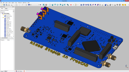
That is cool shiat.
DOn't even think about AutoDesk, mostly cause of the Price and the move to subscriptions services.
I have been demoing a few trials just for fun, wondering if I wanted to drop the coin.
I DO NOT!
AutoCad is $120/month sub service, which is renewable by the month, so you have a project, sub for a month and hope to get it done.
If you hurry you can buy AutoCad single use license for ~$4,600. Yeah no shiat!
You can also buy these specialized Suites. I tried AutoDesk Inventor 2017 for the front door model
I re-linked the vid, well just cause its cool, and to say:
"It took me about 3-4 times longer to model this and create the presentation, than it would have if I used FreeCAD)"
For a WISIWIG, dumbed down UI, the person who designed it was also "dumbed down"
Inventor is a total POS and totally worth the price of ~$235/month.
And jump on this deal:
Product Design Suite Premium perpetual license$5,775 SRP†
After July 31, 2016, new perpetual licenses and subscriptions will not be sold. Learn more.
AutoDesk is changing everything around, don't expect any price drops.
One drawback on FreeCAD. AutoDesk makes it difficult for them to create DXF and DWG files (The core type of CAD files).
I bought a license too Tiega file converter, ~$40 lifetime, which FreeCAD easily integrates. Take that AutoDesk!
Depending on your CAM person, they may/will need a specific type of file to start with. Usually DXF.
But SVG (Scalable Vector Graphics) files seem to be an accepted standard as well, which FreeCAD exports as well (along with many others)
Any CAM operator worth his salt will be able to help you get the final file set-up, and provide you with general guidelines (like how to code each layer->intended shade, etc.)
So there is my two sense on CAD software...
Cheers
Similar threads
- Replies
- 80
- Views
- 4K
- Replies
- 6
- Views
- 552

