• Welcome to Overclockers Forums! Join us to reply in threads, receive reduced ads, and to customize your site experience!

"MCP" Waterblock Concept

Overclockers is supported by our readers. When you click a link to make a purchase, we may earn a commission. Learn More.

Captain Slug

Helpful Senior Member
Joined
May 23, 2001
Location
Asteroid B-612
"Nazca" Waterblock

I've been wanting to design a waterblock for a while now. Regardless of whether this amounts to anything or not I'm designing what I can based around what tools I have access to (Manual Mill, Machine Lathe, Drillpress).
Just trying to get feedback on my design. Hit me hard because I've never done this kind of design work before and just wanted to get this concept out in the open. The aim is low restriction, but more turbulance could be added to the fin design by using an alternating drill-hole pattern.
mcp-block_0.jpg
mcp-block_1.jpg

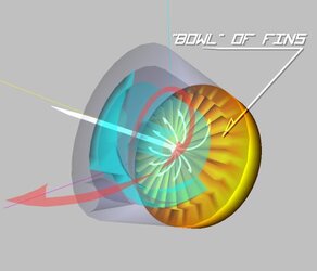
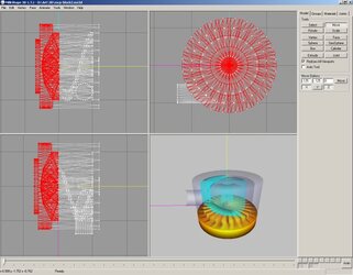
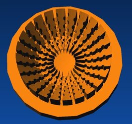
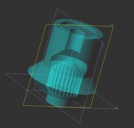
The copper base is 2.5" in diameter with a step on the underside. The acetal top will bolt to the base from the underside. I didn't add the O-Ring to the model but there will be one there.

The "bowl" is cut into the base using a slit saw. The barb sizes are 1/2" ID (but could be larger). The inlet feeds directly into the center and then exits around the edges of the fins, then is channeled to the outlet.
 
Last edited:
It wouldn't be a very expensive block to make since the base is fairly simple.
I don't have any specific plans to makes these as-of-yet since
a) I don't have a rig that I plan to water-cool
and
b) I have too many projects going on at the same time
It's just an exercise in "what-if" for the moment.
 
Captain Slug said:
It wouldn't be a very expensive block to make since the base is fairly simple.
I don't have any specific plans to makes these as-of-yet since
a) I don't have a rig that I plan to water-cool
and
b) I have too many projects going on at the same time
It's just an exercise in "what-if" for the moment.
If you need some testing on a A64 platform I'll be glad to do it when you make one :p
 
Looks interesting, I've never seen a circular block before (that doesn't really mean much though). How are you gonna mount it?
 
I don't think I'm quite understanding the path of the water. It comes in through the top, channels out via those slits you cut in the coin that's on top of the block. Then, travels up and out along the sides, assisted by the blue spiraled piece to the outlet which is coming out the side. Is this right?

I'm not too keen on fluid dynamics, but wouldn't some of the water travelling through the slits be moving slower than others (namely, the slits leading directly underneath the blue spiral)? It seems that it would have an adverse effect on flow for that portion of the block unless a sufficient vortex can occur in that outer chamber.

P.S. - I love your casework.
 
5|*42 said:
Looks interesting, I've never seen a circular block before (that doesn't really mean much though). How are you gonna mount it?
Zalman and a few other manufacturers have milled blocks and I've seen a few custom-made ones milled from rods of aluminum.
I was thinking the mounting plate could bolt onto the underside lip.
Luftwaffle said:
I don't think I'm quite understanding the path of the water. It comes in through the top, channels out via those slits you cut in the coin that's on top of the block. Then, travels up and out along the sides, assisted by the blue spiraled piece to the outlet which is coming out the side. Is this right?
That's correct. And yes the pressure will be a tad uneven, but very few blocks are designed with a single flow-path.

The problem could be alleviated slightly if I were to simply put the outlet on the top of the block. I'll try to figure out a way to do that without making the block more difficult to machine.
 
Last edited:
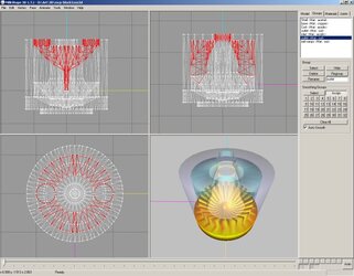
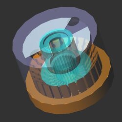
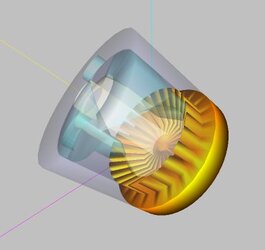
Design revision with one inlet and two outlets, all located on the top of the block. Fin pattern condensed for even pressure distribution.
mcp-block_2.jpg
mcp-block_3.jpg
I think I'll dub this one the "Crater" Block. :D
 
Last edited:
Had a conversation with SewerBeing concerning the design and some theoretical revisions came up.
1. Increase efficiency of block when paired with a CPU with IHS by by dividing inlet channel into 24 individual small-gauge channels targeted to each channel on the waterblock.
2. With the above change, plug the center of the block so that the flow pattern for each channel is seperate.
3. Potentially add a drill-pattern similar to the one found in the Dangerden waterblocks.
ddTDXcu1.jpg


The end result would be a hybrid of a Storm and a Dangerden RBX with 4 times the number of channels. It wouldn't however require a super-restrictive inlet.

I need a more complicated CAD package to revise the design any further.
 
Very nice Captain Slug, I don't know much about WC'ing but would this be a high end block? You should look into AutoCAD its self or borrow a copy from a friend.
 
It wouldn't be expensive to produce but theoretically it should have high-end C/W performance. I'm avoiding having to use CAD/CAM as much as possible to keep the cost down to just the materials since I have free access to everything other than CAD/CAM.
 
Captain Slug said:
Had a conversation with SewerBeing concerning the design and some theoretical revisions came up.
1. Increase efficiency of block when paired with a CPU with IHS by by dividing inlet channel into 24 individual small-gauge channels targeted to each channel on the waterblock.
2. With the above change, plug the center of the block so that the flow pattern for each channel is seperate.
3. Potentially add a drill-pattern similar to the one found in the Dangerden waterblocks.
ddTDXcu1.jpg


The end result would be a hybrid of a Storm and a Dangerden RBX with 4 times the number of channels. It wouldn't however require a super-restrictive inlet.

I need a more complicated CAD package to revise the design any further.


You are gonna need to mess with the fin height, jet size and number of jets or this block is going to be a dud(those calculations are beyond me). Just look at the overclockers.com WW review, just a slight change in channel width made a big diff.

I always wanted to see a combination of jet and fins.
 
Yeah, well understood. The width of the channels will partly be determined by the slit saw blade but I definitely won't be going smaller than 1mm.
 
Alibre!
mcp-block_4.jpg
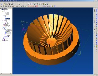
I'm now remodeling the block in the same CAD package that the machine shop uses so that if the shop doesn't have to tools I think they do the block can be edited with just a few clicks to show what I would be making. That and it can subtract, unlike Milkshape which is not at all a CAD program.

Edit: Mmmmm, Cheese
mcp-block_5.jpg
 
Last edited:
Hmm, this is starting to take shape into something actually feasable. :p I say CNC one out and test it yourself. Then if it murders the competition, it's time to make some money. :)
 
Wow, I've never used real CAD before. It's quite awkward since I can't set locations for things as easily but everything else is quite speedy.
Here's the jet collimater, which is actually two seperate lathed pieces joined together
mcp-block_6.jpg
 
Last edited:
And everything put together. Woohoo!
mcp-block_7.jpg
Pretty spiffy for a days work huh? The inlets and outlets are 3/8" NPT so using 1/2" barbs and 1/2" ID tubing will be a piece of cake.
 
Last edited:
The problem is that right above cpu you don't have any pins or fins so that is the weak point.
I have curved fins at my block for increasing the turbolence:
mcw9.jpg
 
eddy you should look at the completed design also the inlet is more of a jet.

Personally I think this design is either a good one or a miserable one although if you decide to test it out slug I am willing to be a guinee pig.

Finally is the CAD program that you are using by chance solid works?
 
Amazing job. I also wouldnt mind testing this out. How much do you project it will cost to make? Any chance of it being mass produced if results are good?
 
Back