• Welcome to Overclockers Forums! Join us to reply in threads, receive reduced ads, and to customize your site experience!

C and Arduino help

Overclockers is supported by our readers. When you click a link to make a purchase, we may earn a commission. Learn More.
1) That is a large part of what setting the pinMode to INPUT does, yes. What it does is tell the Arduino that it should look at pin2 rather than trying to change what pin2 is doing. It can still source some voltage, but very little actual current.

In the fritzing diagram, the button's two pins on the right are connected internally, as are the two on the left.
In that diagram voltage goes to the button and stops there.
The resistor to ground makes sure that anything that leaks out the Arduino pin and/or is captured from the general magnetic fields is sent to ground so the Arduino pin cannot see it.

When the Arduino looks at the pin (digitalRead,2) it sees no voltage, and returns 0.
If you press the button voltage goes through the switch to the Arduino pin side, enough to overwhelm the resistor (if it's a high resistance, don't do that circuit with a 1 ohm resistor or something!), so when the Arduino looks at the pin it sees 5v and returns 1.

The two lines on the right connect the power rails on each side of the breadboard to each other, so that both 5v lines are connected and both ground lines are connected.

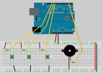
Excellent, that clears a lot up. So in this case the two wires on the right really don't do anything but some people tend to connect the two rails out of habit?

And the button bridges sideways when pressed?

So the digital input pin can read 5v when the button is pressed and you can use this in if/else program loops.
 
OK on to a new project where we're making speakers buzz...
I understand the basic loop function for making it buzz on and off for 1 second at a time. They gave us the code for that.

We are, however, tasked with re-writing it including a "utility function"
void buzz(int targetPin, long frequency, long length);
Where targetPin is the speaker pin, frequency is the frequency of the note
and length is the length of time.

So do we still use void loop() or do we completely replace that? I'm going to google "utility functions" now but I'll probably still need a lot of help here...

Dammit, I've just spent like an hour getting nowhere on this....I understand you are required to always have the loop function so I've kept that in....but I'm not sure about this utility function, do you have the "for" statement in there or keep that in the loop. Then this utility function is supposed to return variables to the loop function or something? I have no idea how to code that....
 
First off, did your instructor mention the "tone" function? He's having you reinvent the wheel here. Not necessarily a bad idea though really, it's good practice. I don't think he'd like it if you used the tone function :D

Anyway, about functions:
They confused the hell out of me, too. Your teacher really ought to have explained about 'em, but here you go:

A function gets it's own section, it can have specific variables passed to it by the call from void loop, and it can return variables as well.

First an example with variables headed to the function, but not back:

Code:
void setup(){
  for (byte x = 2 ; x < 14 ; x++){  // Set pins 2 through 13 as output
    pinMode(x, OUTPUT);
  }
}

void loop(){
 //Whatever it is your main loop ought to be doing, beyond calling the function, if anything
 
snazzyFunction(4,3000,1000); // the function call.
 
 //Other stuff in the main loop to happen after the function call
 
}


void snazzyFunction(int targetPin, long frequency, long length){
  //do stuff!
}
Note that the function is a "void", not a variable, this allows you to call it without assigning a variable to the output.
As a total sidenote, I don't see any reason to use a long for frequency, humans can't hear the >32kHz stuff anyway. No reason not to at this point, though off in the distant future you'll be wanting to use the smallest variables that work so you can conserve ram space.

Same basic example, but returning a variable as well:
Code:
void setup(){
  for (byte x = 2 ; x < 14 ; x++){
    pinMode(x, OUTPUT);
  }
}

void loop(){
 //Whatever it is your main loop ought to be doing, beyond calling the function, if anything
 
int result = snazzyFunction(4,3000,1000); // the function call.  The variable returned goes into result
 
 //Other stuff in the main loop to happen after the function call
 
}


int snazzyFunction(int targetPin, long frequency, long length){
  //do stuff!
  int resultToSend = targetPin * frequency / length; //just because it has to be something)
  return resultToSend;  //send resultToSend back, it gets plopped into whatever variable called the function
}
Note that we are assigning the function to a variable, and that the function itself is an "int" rather than "void". This allows it to shuffle a variable back to the main loop, which will fill the variable you assigned it to.
It doesn't have to be an int, either. The type of variable and the function ought to match though.


If you want to hang out in the function for a while you'll need a for loop in there, otherwise it'll execute once and head back to void loop.
 
Last edited:
I think we move on to "tone" after this first part is done.

So the idea is to put the loop inside the utility function and then call the utility function from inside void loop?

And in this case the utility function would be a void function? It doesn't return a variable as output?

If those 2 statements are true....then I can probably come up with the code now....albeit very slowly.
 
Yup, and yup again!

Now that doesn't mean you can't make it an int in both spots or some such, but you don't have to as you don't have to (I wouldn't).


Has InstructorDude talked about delayMicroseconds()?
If not, it's exactly the same as delay, except it delays for microseconds instead of milliseconds.
What's a microsecond? A microsecond is one millionth of a second, as opposed to a millisecond (which delay uses) being one thousandth of a second.
So delay(1) and delayMicroseconds(1000) are the same.
The number gets huge right quick if you want more than a few milliseconds with microsecond accuracy of course (delay(500) and delayMicroseconds(500000) for half a second), but you can also go well lower than one millisecond.

Not really but I'm an online gamer so I'm aware of ping (milliseconds)...and I figured there was a million microseconds in a second. For now I'm just trying to work out basic code for this one.

/*
*This program will play a tone at a specified frequency for a specified period of time.
*/

void setup(){
pinMode(targetPin, OUTPUT); //set a pin for buzzer output
}

void loop(){
long delayValue = 1000000/frequency/2;
long numCycles = frequency * length / 1000;

buzz(2, 523, 1000); // the function call (calling void buzz)

}

void buzz(int targetPin, long frequency, long length);

for(long i=0, i < numCycles; i++){
digitalWrite(targetPin,HIGH);
delayMicroseconds(delayValue);
digitalWrite(targetPin,LOW);
delayMicroseconds(delayValue);
}
delay(1000); //delay for 1 sec before looping again
}

How does that look? Heaven forbid I have to make it a keyboard next...
 
Looks pretty good, the "void buzz(int targetPin, long frequency, long length)" line needs a { at the end instead of a ;, and targetPin needs to be defined, and the delayValue and numCycles should be inside the buzz function (where they are right now they cannot see "frequency" or "length", those variables are created and populated only inside the buzz function.

In void loop just put the buzz function call. I'd put the one second delay in void loop as well, it's the one directing things and the buzz function should just be following orders.

/*
*This program will play a tone at a specified frequency for a specified period of time.
*/

int targetPin = 2;

void setup(){
pinMode(targetPin, OUTPUT); //set a pin for buzzer output
}

void loop(){
buzz(2, 523, 1000); // the function call
delay(1000); //delay for 1 sec before looping again
}

void buzz(int targetPin, long frequency, long length){
long delayValue = 1000000/frequency/2;
long numCycles = frequency * length / 1000;

for(long i=0, i < numCycles; i++){
digitalWrite(targetPin,HIGH);
delayMicroseconds(delayValue);
digitalWrite(targetPin,LOW);
delayMicroseconds(delayValue);
}
}

I hope I fixed everything......now onto the keyboard concept. We need 3 buttons and for it to play a different tone as each is pushed. I guess I would start by copy/pasting the code.....then adding in the 5V input circuit stuff to test for button presses....then it'll be some sort of big if/else statement?
 
How's this look for a pushbutton keyboard concept? I think I'm getting used to the idea of the 5V and GND rails.

23h5en9.jpg
 
The code looks good and compiles except for a type here "for(long i=0, i < numCycles; i++){" That "," should be a ";".
That's the only issue though (I haven't actually tested it, but it compiles which is a very good start).

The buttons should work, though a slightly more complicated setup is generally recommended for better resistance against interference and false presses and such.
Lets see if I can make fritzing work to do a picture for you...
At the very least, put a resistor (something between 470ohm and 33k) on the line from the +5V rail to each switch. That way if you forget to set the pin to INPUT or something you don't have a dead short that blows the chip to hell.
 
Ok here we go.
fritzing buttons-speaker.png
The arduino pin and a resistor are both hooked to one side of the switch, the other side of the resistor is hooked to 5v. Use a 1k to 10k resistor.
The other side of the switch is hooked to ground.

With the button at rest (untouched) digitalRead(inputPinWhatever) will return 1.
With the button pressed it will return 0.

This setup is hardened against interference and protected against overcurrent, you would have to work fairly hard to fry the arduino with it. If you wanted to be really safe you could make the 5v to switch resistor (the pull-up resistor) a 10k and connect the other side of the switch to ground with a 1k resistor. At that point you simply could not fry the arduino with it even if you tried.
That's overkill though.
 
The code looks good and compiles except for a type here "for(long i=0, i < numCycles; i++){" That "," should be a ";".
That's the only issue though (I haven't actually tested it, but it compiles which is a very good start).

The buttons should work, though a slightly more complicated setup is generally recommended for better resistance against interference and false presses and such.
Lets see if I can make fritzing work to do a picture for you...
At the very least, put a resistor (something between 470ohm and 33k) on the line from the +5V rail to each switch. That way if you forget to set the pin to INPUT or something you don't have a dead short that blows the chip to hell.

Question: If you have resistors in a circuit...does it not matter where they are in relation to the other components? Like if you have them before or after the buttons/LEDs/etc?

In this case could I just change those 3 small red wires (which correspond to each button) to resistors?
 
Ok here we go.
View attachment 98888
The arduino pin and a resistor are both hooked to one side of the switch, the other side of the resistor is hooked to 5v. Use a 1k to 10k resistor.
The other side of the switch is hooked to ground.

With the button at rest (untouched) digitalRead(inputPinWhatever) will return 1.
With the button pressed it will return 0.

This setup is hardened against interference and protected against overcurrent, you would have to work fairly hard to fry the arduino with it. If you wanted to be really safe you could make the 5v to switch resistor (the pull-up resistor) a 10k and connect the other side of the switch to ground with a 1k resistor. At that point you simply could not fry the arduino with it even if you tried.
That's overkill though.

So with yours, the current always flows to all 3 pins? So digitalRead(1) by default...and when a button is pressed that pin will then receive no current and digitalRead(0)?

And so then I would code it to play the tone when digitalRead(0)?
 
Question: If you have resistors in a circuit...does it not matter where they are in relation to the other components? Like if you have them before or after the buttons/LEDs/etc?

It varies on the circuit. LEDs don't care as long as there is a resistor somewhere to limit the flow through the LED.
Button circuits generally care, it can be fatal to things to have the resistor in the wrong place sometimes. And yes, just swap the short red wires for resistors. You may find that the pin sometimes returns 1 even without the button pressed however. You could fix that with another (higher resistance) resistor between the Arduino side of the button and GND. That would be a pull-down resistor that dumps any leftover charge when the button is released.


So with yours, the current always flows to all 3 pins? So digitalRead(1) by default...and when a button is pressed that pin will then receive no current and digitalRead(0)?

And so then I would code it to play the tone when digitalRead(0)?
Exactly, on both counts.
 
It varies on the circuit. LEDs don't care as long as there is a resistor somewhere to limit the flow through the LED.
Button circuits generally care, it can be fatal to things to have the resistor in the wrong place sometimes. And yes, just swap the short red wires for resistors. You may find that the pin sometimes returns 1 even without the button pressed however. You could fix that with another (higher resistance) resistor between the Arduino side of the button and GND. That would be a pull-down resistor that dumps any leftover charge when the button is released.


Exactly, on both counts.

But when one is pressed...won't they all be digitalRead(0) ? I thought when current goes to ground, it ALL goes to ground and thus there would be none left over for the other 2 pins?
 
That's what the individual resistors are for, they act as a voltage drop for the switch.
Essentially if you short a circuit to ground, everything past the highest resistance point will show zero voltage.
So all three resistors will always have 5v on the 5v side, and the switch side will be pulled to 0v by the switch being pressed.

Now if we left the resistors off you would be taking the entire 5v supply and shorting it to ground. If you were lucky the regulator would hit OCP or SCP and shut down, if it didn't something would melt and/or burn.

If we put the resistors on the other side of the button, the button would always see 5v as it is before the resistor.

OK I'd be lying if I said I totally got it....but I get the basic idea...when you push any button, the 5V goes to ground rather than to the relevant pin.
I'll probably start trying to figure out the code tomorrow....lol too much study for one Saturday.
 
Back