• Welcome to Overclockers Forums! Join us to reply in threads, receive reduced ads, and to customize your site experience!

Fan Controller / PWM Booster / Regulator / Converter / Etc. Thread!

Overclockers is supported by our readers. When you click a link to make a purchase, we may earn a commission. Learn More.
That would in fact be awesome, no doubt there. It'd also cost probably $300 to $500 and require at least four PCIe 6P or two 6+2P power connectors.
Hell just in parts that'd be somewhere between 150 and 200 bucks.

Bit beyond my abilities at the moment. To be more specific, it's a bit beyond what I have time/money to develop without a salary or hourly wage to do it :D
 
The Arduino board has USB connectivity to the host PC built in. What it doesn't have is 10 separate PWM outputs so that's what the external logic is for. (I suppose you could just tie all the PWM outputs together and run a buffer off one Arduino PWM...) The built in ADC is good enough for analog temperature sensors (plus a mux if you really have a lot) and it has SPI and I2C for digital temperature sensors. You could connect a text based or graphical LCD with built in controller, but for a full fledged touchscreen, you might as well get a cheap phone or tablet (used is great for that) and use that for the display, like how I'm doing it in my machine.

There are fan controller chips out there that take care of the PWM and RPM signals, interfacing with the microcontroller via I2C.

To get the PWM commanded by the motherboard, you could either low pass filter it and read it as an analog value or you could set up a gated counter. I suggest the former as it's much easier.

If you wanted to go fancy, put a Hall sensor on the power wiring (the snap on type are great for this) and use that as an input to the fan controls so they can react faster than the thermal time constants. Completely overkill for water cooling and not really necessary for air cooling, but why not?
 
Or start with a $20 TI IoT launchpad (pin map here) and control the whole thing over ethernet, with more PWM and analog and SPI and I2C than you can shake a stick at. Plus it'd actually have enough RAM and storage to use all the stuff.

While it could probably be done with an Arduino, it'd be a far larger pain in the rear than it is worth. There are much better MCUs out there to do it with.
 
Last edited:
Hey guys, thought I would contribute.

I'm currently designing and coding a 9-channel PWM USB fan controller using a PIC18f2455/2550.

Each Fan can be individually controlled. User interface shows RPM/PWM for each fan and PWM/RPM for each fan can be adjusted.

It's very basic for now, but fully working. Once I finalise the design (and assemble a non-prototype version), I'll be re-writing the software (flashier/sleek design and options?) and firmware (more optimised).

It's also easily scalable to 16 Fan if I were to use a 18f4550 for example.

I haven't worked on Touchscreen/LCDs yet, but a 18f4550 should have enough I/O to do that without sacrificing too many fan channels. I probably won't look into that myself, unless there is a lot of genuine interest/demand for it.

edit: 1 temp sensor to measure ambient temp should be very easy to implement. I'm ordering a few sensors to prototype on my 18f4550 version.
 
Last edited:
I've had a quick look at implementing LCD. There are readily available libraries for monochrome LCD. I reckon it would not be too much effort to do it given current scope. I haven't thought about what would be displayed on it yet. Maybe some ideas?

Picture of hardware setup (3 fans connected atm, easier for prototyping/debugging)
2a960ja.jpg

Picture of win software (input fan#, and duty cycle to set desired PWM.)
j08gmg.jpg
(After I re-write the software, you should be able to: drag a bar to adjust desired setting, switch between %fan speed and duty cycle for adjusting, "name" your fan, "link" fans (i.e. changes in 1 fan will be made to other linked fans, etc)
 
Nice! I like it.

Thanks.

I'll post updates as I progress, although now I'm quite seriously considering implementing temperature sensor (useful) and LCD (just for fun). But that means I'll have to redesign, wait for parts/etc, build a proper prototype, and I don't have much patience haha.

My current schematic is partly hand-sketched and partly drawn on excel, and it's a massive pain to change it (so I've actually given up on that).
256h3rn.jpg

Any recommendations for a good design software that can lay a nice schematic for prototype board as well as printed boards? I really liked http://123d.circuits.io/ because you can search for and add various parts easily (or create your own) , but it's wiring algorithm is REALLY BAD (it won't let me/I don't know how) to manually trace a wire. meh
 
Last edited:
For schematics I really like CADSoft Eagle. It won't show you how to lay it out on perfboard though.
It does have a layout thing for PCBs that you can either etch yourself or send out to a fab house.
 
So I've ordered some more parts, including thermistor and lcd. I won't play around much with the LCD. I've redesigned a board for using the 18f4550.
This will allow:
1) 10 fans individually monitored (tach) and controlled via PWM
2) Measure ambient temperature near the board (presumably inside the case) (Software-side can deal with adjusting fan speed based on temperature)
3) Couple of status LEDs
4) LCD Output (not a priority at this stage)

I'll be working on the software tonight + a little on the firmware-pc communication. i'll post some updates/pictures later.
 
Just another quick update.

I started re-writing the software interface (moving from c# to vb since I don't like dealing with {} and ; ).

Fans can now be controlled using sliders.
28ujml2.jpg
 
555 kit PCBs came in. I'm placing a parts order tonight.

PCB-Top.jpg
PCB-Bottom.jpg

Doubles as a SMD practice board, all the parts are big enough to find if you drop them (don't try it on carpet, though) and super super cheap to replace should you lose or destroy them.


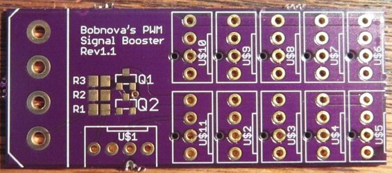
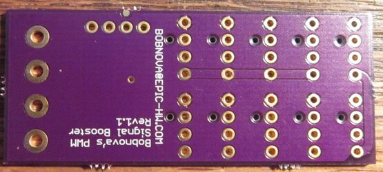
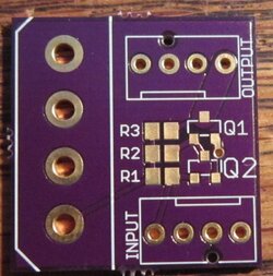
Got the next revision of boosters as well:

bigBooster-top-unassembled.jpg
bigBooster-bottom-unassembled.jpg


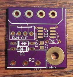
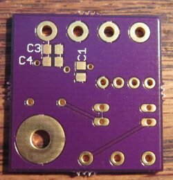
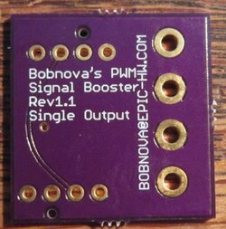
New product! Single output boosters. This is aimed at people that want to do their fan splitting in the cables rather than on a PCB. Good for people that want to power their fans via Molex connectors and just need a boosted PWM signal.

smallBooster-top-unassembled.jpg
smallBooster-bottom-unassembled.jpg

This is the highest powered booster yet, it should be able to run something over a thousand fans if the fans are built to Intel specs.
Its capable of powering solid fans as well, the female fan connector will die before the board will. From a purely board/pin header standpoint, it'll do the 11 amps of the Molex spec. Female fan headers die somewhere between 3.5 and 6 amps though.
 
Yeah!
It's sort of a silly rating, but by the spec each fan feeds [email protected] into the PWM pin, the booster or controller or motherboard needs to pull that to ~0v. The MOSFET can do ~4 amps, the trace is good for around that, as is the pin on the header. That gives ~800 fans.

In reality the fans will supply more or less than 5ma, the MOSFET will be able to handle more or less than 4a (probably more), etc. but yeah, far more fans than you want to listen to!

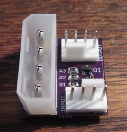
I assembled one and it works great!
smallBooster-top-Assembled.jpg
Look for it in my classies thread shortly.
 
jw but you thought of or have you done a booster-controlled board? pwm input to 4 outputs with single control for all 4 fans. would be like the input signal gets controlled to the 4 outputs.
 
That's what the ten port booster/splitter does essentially if I'm understanding you correctly. One PWM signal comes in, that same duty cycle and frequency goes out to 10.
 
no, take your pwm fan control board coupled to a 4 pwm outputs. in this setup one reo to control all 4 fans at the same time. signal would be controlled before being sent out to the 4 ports.
 
Ahh OK, so a four output fan controller.
Haven't built one, could easily enough.
 
Back