- Joined
- Dec 6, 2010
-
Welcome to Overclockers Forums! Join us to reply in threads, receive reduced ads, and to customize your site experience!
You are using an out of date browser. It may not display this or other websites correctly.
You should upgrade or use an alternative browser.
You should upgrade or use an alternative browser.
Network upgrades.
- Thread starter don256us
- Start date
- Joined
- Jul 17, 2003
- Thread Starter
- #22
Progress on this project. I decieded that I want to color code my patch cables. I know, too fussy. I get it. We don't do it at work and we need to. I don't need it at home but I'm gonna. Did some google searches to find any standard coding out there. I found that there are some general guidelines but none are required so I ditched that and started to create my own.
Pattern based on the device that the cable goes to. Tentatively here is what I think I will go with:
Red = Infrastructure. Switches, APs, Modem, Router, etc.
Blue = PC or end user machine.
Yellow = Server
Green = Printer
White = Camera
I'm open to suggestions as I won't be doing this for a few months yet.
The other issue that I'm giving thought to is how to attach my switches. Currently, and in my current rebuild plan, I'm cascading my switches. Now for a small network like mine, that's fine. But I'd like to mimic a more "best practice" for this. My current plan has: Modem > Router > Switch > Switch > Switch. If it doesn't make sense to correct this I won't but I'd at least like to explore the idea. Even if I don't change my design, I'd like to go through the thought exercise.
- Joined
- Dec 6, 2010
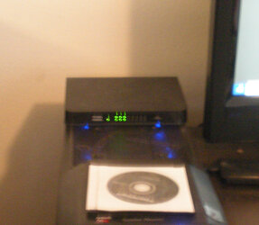
I have modem-> router-> 16 port switch
16 port switch:
port 1 to router
port 2 to PC
port 3 to 5 port switch
port 4 to 8 port switch
port 5 to 5 port switch
port 6 to 5 port switch
p.s. all switches, router and the connection between the modem and router is 1Gb
Sorry for the blurring, but if I use the flash on my camera, the led's get washed out.
Last edited:
- Joined
- Feb 7, 2003
- Joined
- Jul 17, 2003
- Thread Starter
- #26
OK. So I got a used 24 port PoE Gen 1 Ubiquiti switch in the mail yesterday. I'm home alone for the weekend so I think that I will install it tonight. I'll take pictures and post. This will conclude my network updates. I can now get those patch cables in proper lengths to make it look nice. I'm looking forward to that.
More in the next few days.
Realized I need the SFPs too. I just ordered those and will get them tomorrow.
More in the next few days.
Realized I need the SFPs too. I just ordered those and will get them tomorrow.
Last edited:
- Joined
- Jul 17, 2003
- Thread Starter
- #27
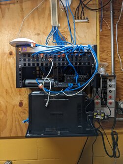
I removed my 16-port switch and installed the 24-port. Below are pictures that look nearly identical. This fall or winter I will spend more time getting the patch cables I want and make this look pretty.
First, the old 16-port.

Now the 24 port.

An issue that I did NOT think about prior to the installation, even though both switches are the same gen (gen 1) and both are Ubiquiti, they have a very different depth to them. I took out the 16 port and went to install the 24 port switch. The power cable hit the back and wasn't even close to letting me bolt it down to the rack. I pulled out a 90 degree power cable and it is much better. I got the one side bolted well but I think I will get some washers as small spacers and longer bolts (screws) to make it more secure.
I also bought a 1U blank that I will attempt to cut in holes and with the help of friends with 3D printers, make brackets for the UniFi Cloud Key and the 2.5 Gb switch. Lift them off of the shelf and hide more cable.
First, the old 16-port.
Now the 24 port.
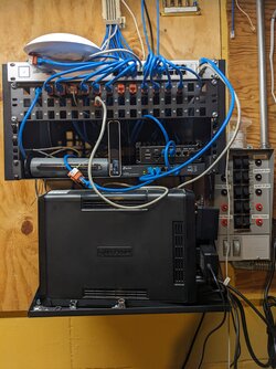
An issue that I did NOT think about prior to the installation, even though both switches are the same gen (gen 1) and both are Ubiquiti, they have a very different depth to them. I took out the 16 port and went to install the 24 port switch. The power cable hit the back and wasn't even close to letting me bolt it down to the rack. I pulled out a 90 degree power cable and it is much better. I got the one side bolted well but I think I will get some washers as small spacers and longer bolts (screws) to make it more secure.
I also bought a 1U blank that I will attempt to cut in holes and with the help of friends with 3D printers, make brackets for the UniFi Cloud Key and the 2.5 Gb switch. Lift them off of the shelf and hide more cable.
- Joined
- Dec 6, 2010
Don't stop at 24, go with 96 port switch, this way you can have a ton of unused ports doing nothing 

- Joined
- Jul 17, 2003
- Thread Starter
- #29
I just purchased a 5-pack of the 8inch 3-prong 110v extension cables. (link for reference only. Not tested nor vetted. Only purchased.)
I have a problem where I have a 1500 amp hour UPS. It should keep what I have running for up the three hours (when it was new) in the event of a power outage. As usual, these low voltage DC power devices have power bricks that don't allow me to plug more than two in and one is wonky to make it fit. This meant that when I have a power blip, and I get a lot of them, some of my gear goes down thus disrupting my network and sometimes not recovering on it's own.
This 5-pack will allow me to plug in a 250 watt, PoE switch, modem, 8-port 2.5 Gb switch and router. Very little by means of power usage. Since I don't use all of the ports on the 24-port PoE switch and even fewer use PoE, I use little of the 250 watt max that it can use.
I still need toget screws for the new switch and some spacers to fasten it to the rack properly. Not my top project going on but I'm doing the little parts when I can.
- Joined
- Sep 25, 2015
You don't want to be putting pressure on the power cable. I use these Depth Extenders to bring things out a few inches...work great:
https://www.amazon.com/gp/product/B01GGKM4S8/ref=ppx_yo_dt_b_search_asin_title?ie=UTF8&th=1
https://www.amazon.com/gp/product/B01GGKM4S8/ref=ppx_yo_dt_b_search_asin_title?ie=UTF8&th=1
- Joined
- Jul 17, 2003
- Thread Starter
- #31
I came back to this thread to update. I see that I had stated that I was going to order the new patch cables back in November.... of 2022! I did not. I did however order them last night. They will be here by the weekend and I will start to swap them out.
My UPS went out as shown in pictures above. This caused my wife to have to figure things out while I was at work. She called and I tried to walk her through it all. She couldn't get it tow work.
When I got home, I messed around and ended up bypassing the UPS. I went to testing everything out and couldn't make anything work. Turns out, because I don't have proper length patch cables, the patch cable for my computer was unplugged. That was the last straw. Time to set this up properly.
Now (after a full week) if I could get Cyberpower to respond to my support ticket.
I'll take pictures and share them. If you want to know what it all looks like today, see the old pictures above. Same same.
- Joined
- Jul 17, 2003
- Thread Starter
- #32
Joke's on me. I called Cyberpower and they have been trying to reach me since the day I submitted the request. At thier suggestion, I looked in my junk mail. Tech took quick care of me and got my issue moving forward.  I just have to get out of my own way here.
 I just have to get out of my own way here.
Similar threads
- Replies
- 1
- Views
- 527
- Replies
- 4
- Views
- 703
