Pencil mod ms7254 isl6566 pwm, bsel mod, vid mod, vreg, vdroop, vcore mod, how?
(I SOLVED vcore 1.4 but the instant i overclock beyond 235 fsb the pc stops working, my motherboard max is 800 fsb but with duo core pentium i could overclock to 280 fsb): I did the correct vid pin mod and raised the vcore up 1.4. If you have sometrhing to say please say it, thanks. http://forum.xcpus.com/f45/lga775-series-vcore-mods-202.html)
My issue now: I have enough vcore 1.4 but computer can't function at above 235 fsb, what is the issue?
Hi guys! Thanks for looking at this post.
I would like to be able to play games smoother and watch movies smoother and i guess having more voltage can get this pentium d945 up from 3.4Ghz to 5Ghz.
How do i do: 1. BSEL mod (does this increase vcore as well?) 2. VID mod 3. Voltage regulator chipset mod 4. Any mod.
The mainboard is from year 2006 and has award-phoenix bios rev 1.05. There are bios updates that i am not sure offers any ability to mod the vcore and also i didn't manage to flash the bios successfully with these updates.
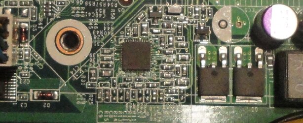
I dont know how to do the vdroop on ms7254 mb. I dont know which resistor to lead pencil. I penciled most of the resistors sourrounding the ISL6566 chip but i didn't pencil any pin on the chip but no change to vcore and vdroop during load or idle. Penciling one of these resistors however makes the PC not booting. So i erased the lead and it booted again.
Vcore range is 1.26-1.185.
The black chip is ISL6566. Datasheet is here:
https://docs.google.com/viewer?a=v&...JaQyWr&sig=AHIEtbQT7R4btucFnBAxHJtkDB47ncmIVQ
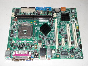
Cpu is intel d945 3.4 ghz, dubble core, stock FSB 800 Mhz. Fsb stable up to 231 (it's not above 4Ghz). No option in bios to raise any vcore or anything. This mobo name is also 0A48. It was installed and came with DX2200MT HP computer. I tried to pad mod the cpu with lead pencil but not successing.
Every help appreciated. Thanks guys.") You are free from responsibility.
You are free from responsibility.
(I SOLVED vcore 1.4 but the instant i overclock beyond 235 fsb the pc stops working, my motherboard max is 800 fsb but with duo core pentium i could overclock to 280 fsb): I did the correct vid pin mod and raised the vcore up 1.4. If you have sometrhing to say please say it, thanks. http://forum.xcpus.com/f45/lga775-series-vcore-mods-202.html)
My issue now: I have enough vcore 1.4 but computer can't function at above 235 fsb, what is the issue?
Hi guys! Thanks for looking at this post.
I would like to be able to play games smoother and watch movies smoother and i guess having more voltage can get this pentium d945 up from 3.4Ghz to 5Ghz.
How do i do: 1. BSEL mod (does this increase vcore as well?) 2. VID mod 3. Voltage regulator chipset mod 4. Any mod.
The mainboard is from year 2006 and has award-phoenix bios rev 1.05. There are bios updates that i am not sure offers any ability to mod the vcore and also i didn't manage to flash the bios successfully with these updates.
I dont know how to do the vdroop on ms7254 mb. I dont know which resistor to lead pencil. I penciled most of the resistors sourrounding the ISL6566 chip but i didn't pencil any pin on the chip but no change to vcore and vdroop during load or idle. Penciling one of these resistors however makes the PC not booting. So i erased the lead and it booted again.
Vcore range is 1.26-1.185.
The black chip is ISL6566. Datasheet is here:
https://docs.google.com/viewer?a=v&...JaQyWr&sig=AHIEtbQT7R4btucFnBAxHJtkDB47ncmIVQ
Cpu is intel d945 3.4 ghz, dubble core, stock FSB 800 Mhz. Fsb stable up to 231 (it's not above 4Ghz). No option in bios to raise any vcore or anything. This mobo name is also 0A48. It was installed and came with DX2200MT HP computer. I tried to pad mod the cpu with lead pencil but not successing.
Every help appreciated. Thanks guys.
You are free from responsibility.Attachments
Last edited: