• Welcome to Overclockers Forums! Join us to reply in threads, receive reduced ads, and to customize your site experience!

PROJECT LOG Project Vitis

Overclockers is supported by our readers. When you click a link to make a purchase, we may earn a commission. Learn More.

Navig

Senior Case Master
Joined
Dec 7, 2003
Project Vitis


Hi all,

I'm kicking off the thread for my latest project, tentatively titles Project Vitis.


My wife is currently using my old project, Jewel Box, but wanted a new case designed specifically for her.


VineandLeafpattern.jpg


She had a general theme in mind--a vine and leaf motif, as in the picture above (from http://www.clipartoday.com/clipart/nature/grassandtree/vine_308268.html).


Hence the title of this project, Vitis, which is the species name for vines (ie grape vines).


We kicked about general design and settled on a case roughly in size and build of my most recent project, Resilience (also known as the R unit during its building phase).


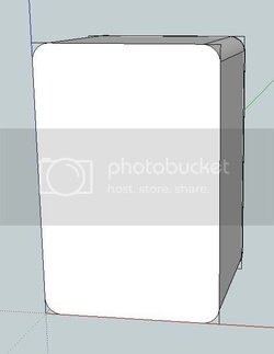
She was not interested in the curvy front panel of my Resilience box, so instead we decided to simplify it into a simple curved corner box a la mailbox or refrigerator.


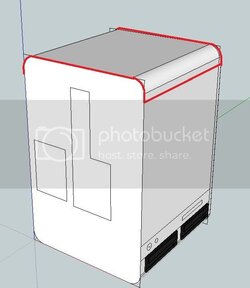
I decided to do a little basic SketchUp to get a feel for the overall shape:


The primary shape was based on this simple profile:


Sidepanel.jpg


A simple upright rectangle with rounded corners (3cm radius bends).


The general shape was going look like this:


Solidblockmodelwithguidelines.jpg


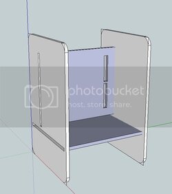
Once again, the internal structure was going to be made from 1/2" MDF sheets, with virtually the same configuration as Resilience:


StructuralMDF.jpg


The surfaces would be made from 1/8" sheet acrylic. My wife specifically did NOT want the clear tinted plastic, so instead we opted for opaque plastic.


A little more on the aesthetic details.

We decided to have the side panels be glossy black.

The front, top and back face panels would all be white.

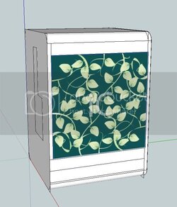
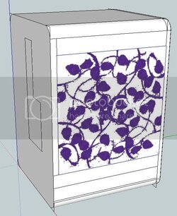
To incorporate the vine and leaf motif, the large front and back face panels would have the vine and leaf motif, like this ghetto SketchUp attempt:


Solidblockmodelwithsurface.jpg


The panel would be white, the vine and leaf pattern would actually be a cut-out from this surface panel, revealing an underneath purple plastic layer


Forgive my awful photoshopping skills, but it would look a little more like:


Surfacewithpurple.jpg


Finally, from a design aspect, I wanted to take all I had learned from my very prolonged Resilience project, and simplify. I wanted the case and the build process streamlined. And with the potential for future reproductions. I'm hoping to complete this project in 2-3 months.


.
 
I always love to see your work Navig, definitely subscribing to this :thup:
 
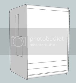
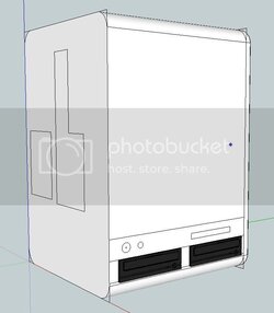
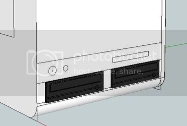
One last Sketchup with the placement of the 5.25 drives and psu:

Solidblockwithbays.jpg


On to construction:


After finishing my previous project, I splurged on some shop upgrades.

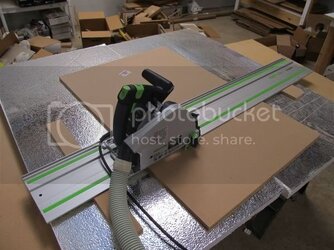
First my new Festool TS55 plunge cut track saw.

Festool.jpg

This tool is one of those that after about 10 minutes of use, you wonder how and why you functioned before it. It really is the ultimate panel cutter.

Step 1) Have a nice large sacrificial table

Step 2) Drop you panel (mdf or plastic) on the table and draw the line you want to cut

Step 3) Line the edge of the track to your line

Step 4) Run the saw down the track.


The simplicity and accuracy is really unbelievable.

Couple of additional tips--I took some worn out pool hose and zip tied it onto the dust port. Use the dust port, it works awesome.

Shim the track with disposable material the same thickness as the panel on both sides so the track lays flat.


Second tool:


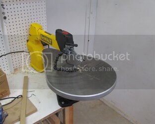
DeWalt scrollsaw.


Scrollsaw.jpg


This thing is great. With moving arm underneath the table and pinless blades, it makes detaching the blade and threading it thru a starter hole, effortless.


.
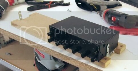
 
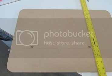
After cutting my square panels with my handy dandy track saw, I set about creating the 30mm radius bends to round the corners.


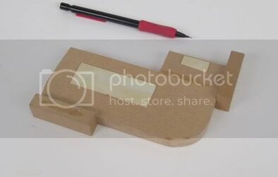
First I created a jig:


Cornerjig.jpg


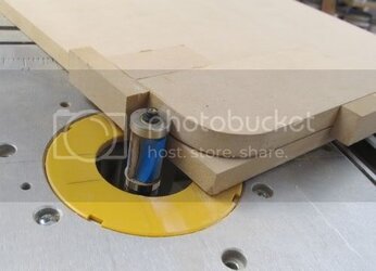
With some simple double stick tape, I attached it to each of the corners:


Cornerjig2.jpg


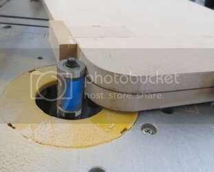
And on my router table and a flush trim bit, rounded the corners:

Cornerjig4.jpg


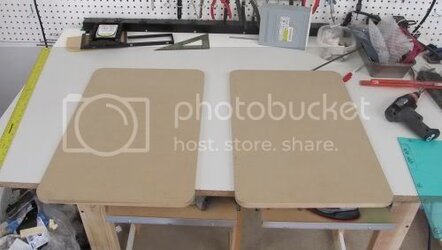
And then I had my 2 side panels with rounded corners:

Sidepanelsmdf.jpg


Most of these techniques I've gone into greater depth when I built my Resilience Project in the build log.


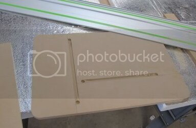
Next it was time to add the dado grooves (slots for the cross panels).

Using a 1/2" Forstner bit, I marked the ends of the dadoes to a depth of 1/4":

Dado1.jpg


And then using the superaccurate tracksaw, removed most of the material of the dadoes:

Dado2.jpg


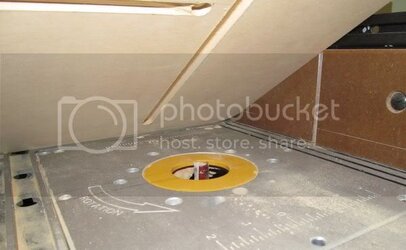
Then to get the full slot, I went to the table router:

Dado3.jpg


By carefully positioning the piece of wood, I could drop the end hole onto the 1/2" bit. Then I would adjust the table fence to run exactly parallel.
Turn on the router and mill out the length of the slot until I hit the other end hole.


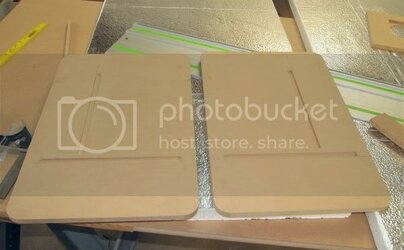
End result: 2 side panels with precise dado slots:

Dado4.jpg


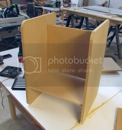
Then I cut up some cross panels, and my structure was taking shape:

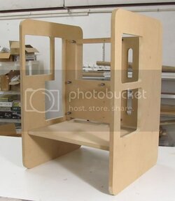
MDFframe.jpg


Notice, because of the dadoes (woodworking 101) the structure has integrity without a single fastener.
 
That Track Saw looks awesome. I'm a sucker for power tools, lol.
 
Looks to be closely related the the "R Unit" in design. Can't wait to see it finished :D
 
Looks to be closely related the the "R Unit" in design. Can't wait to see it finished :D


It's really a simplification of the R unit. After finishing the R unit, my wife liked the overall design and dimensions. The good thing was, after hammering thru the fabrication techniques the first time--now what took me a month to do now takes a few days.
 
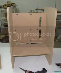
Next I started carving into the structure for all the cutouts:

ShapingMDF1.jpg


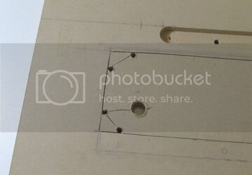
Here's a little tip on how I make sharp corners with a scrollsaw:


MDFcuttingsharpcorners.jpg


The small pre-drilled turning holes allow you to make turns with the scrollsaw blade. This lets you approach the corner, then back out, cut across to the other side and approach the corner from the other 90 degree. You will leave a tiny bit of a ridge at the pre-drilled turn holes, but they are easily sanded away.


Cut out the PCI side hole:

MDFcutting2.jpg


And the rest of the holes:

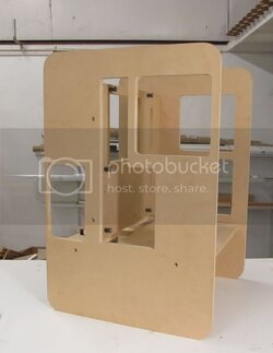
MDFframe2.jpg


MDFframe3.jpg


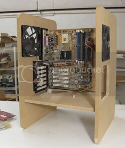
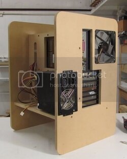
And now I can even put some parts in to make sure everything fits well:

MDFframe5.jpg


MDFframe6.jpg
 
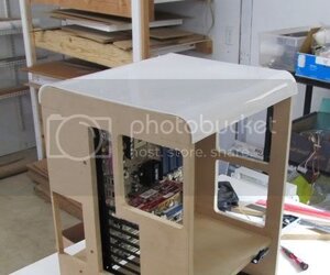
Now that I had my structure put together, I set to wrapping it up in plastic.

I tackled what I knew to be the most difficult task. I planned for a lid on the top of the case which would include both 30mm radius bends.


Toppanel.jpg


I wanted this top panel to have both bends on each end--that way the rest of the panels in this project would be just flat panels.


Altho not as ambitious as my previous Resilience panel, I wanted to improve my plastic bending methods from back then. So I really started experimenting:

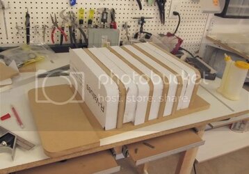
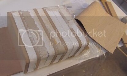
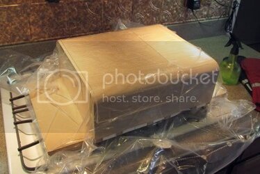
I first started by constructing a mold over which to bend the plastic.


I put together several 3/4" MDF ribs, and then threw some rigid polystyrene panels in between.


Plasticmold1.jpg


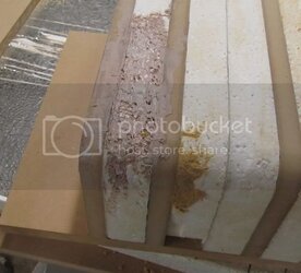
Next I wanted to make a nice uniform surface, so I started to Bondo over the top.


However, I discovered that Bondo in fact dissolves polystyrene!

Plasticmold2.jpg


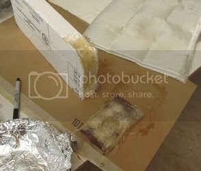
I went for plan B, till I thought about it. And after a little testing, discovered that fiberglass solvents also melt polystyrene:

plasticmold3.jpg


I had 2 options at this point. Try and repair this mold, or scrap it all, lose the polystyrene and start over (probably with mdf and fiberglass).


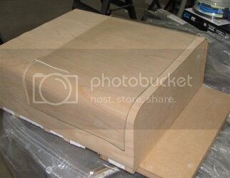
However, after some thought I found a product to salvage this mold: modeling clay:

Plasticmold4.jpg


After smoothing the surface out with some modeling clay, then I decided to lay over a nice uniform sheet of 1/32" thick wood veneer.


At the same time I decided to do a little experimenting with vacuum molding.


I picked up one of those vacuum compression bags (for storing clothing) from Walmart for $10.


Then I applied some spray adhesive to the surface of the mold. Positioned the veneer over it, and placed everything in the vacuum bag.


th_146.jpg

(Click Pic for video)


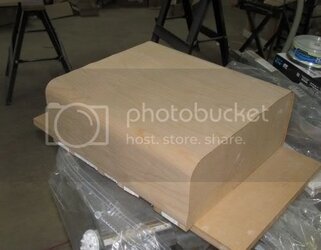
Let the glue dry, and had a nice mold:

Moldsheeted.jpg


This little experiment was so successful that I began to wonder. Could I use it actually bend the plastic over the mold.


The answer yes:


I started with a piece of clear test plastic.

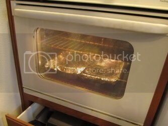
Heated in my oven to roughly 260F.


Plasticinoven.jpg


Threw it onto the mold within the vacuum bag.

Applied vacuum and the voila! Vacuum molded:


Plasticinbag1.jpg


The bag did crease and stretch a little so I think I'll get a few runs before it may actually break under vacuum. But it did a great job.

As soon as the pressure was applied, I spritz'd cold water over the surface to rapidly cool plastic until it was set.


And here was my firs piece of test plastic, looking pretty good:


Pasticbenttrial.jpg
 
Last edited:
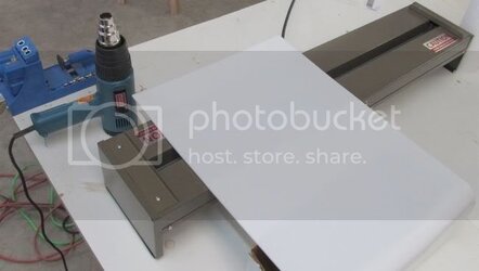
Here was the final method I employed to produce my radius bend plastic panel:


Plasticbendfinal1.jpg

I used a linear strip heater. This is great for making sharp bend, but in order to make a radius bend, I had to keep moving the panel a little and do some re-heating with a heat-gun.


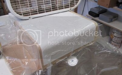
Once I had just the area I wanted to bend up to 260F, I threw into the vacuum mold:


Plasticbendfinal2.jpg


I did one side at a time. Trim the ends and on it goes up top:

Plasticbendfinal3.jpg


.
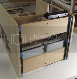
 
Very nice plastic work. That form method looks quite a bit more stable than previous ones. Love the white plastic BTW its so clean looking.
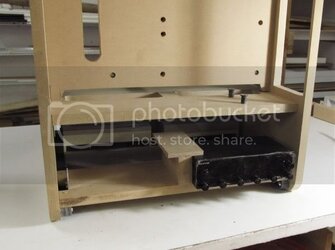
 
Back to working on some of the infrastructure.


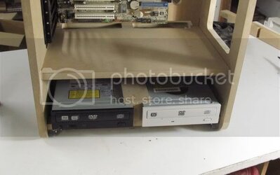
One fun challenge was how to mount 2 5.25 bay drives side-by-side:

525caddysketch.jpg


Because this setup makes it difficult to access the side mount screws squeezed in the area between the 2 drives.


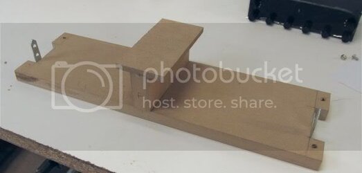
So I built a side-by-side caddy:

525caddy.jpg


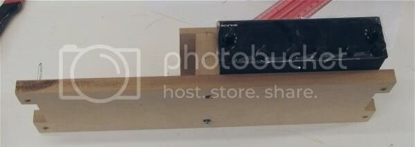
The center hold-down block comes off. You mount the drives with the outside screw holes:

525caddy2.jpg


Then you put the center block on, and it squeeze mounts the center area:

525caddy3.jpg


On the bottom of the case, I mounted 2 mounting rails of 1/2" square delrin rod. The caddies sit on top of these 2 rails mounted with simple thru-screws.


525caddy4.jpg


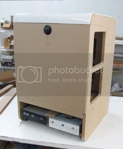
I've got room for 4 5.25 bay devices, 2 in back:


525caddy6.jpg


And 2 in front:


525caddy5.jpg
 
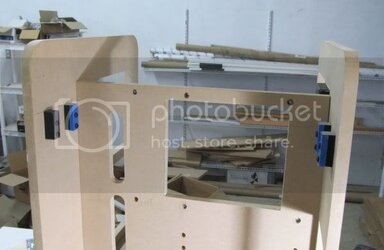
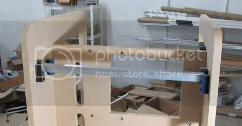
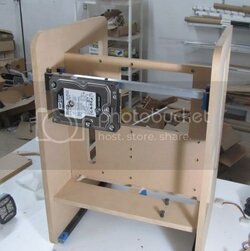
Next I worked on my hard drive racking.


Again, kept it simple.


2 sets of mounting blocks:

HDdrive1.jpg


Each block has 2 mounting screws, plus a threaded hole up top.


HDdrive2.jpg

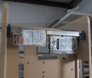
Simple angle aluminum spans length, held in place with 2 thumb screws.


Holes at appropriate lengths to hold drives sideways:

HDdrive3.jpg


Space for 4 drives. Holes for 3.5" or 2.5" drives:

HDdrive4.jpg


.
 
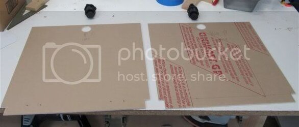
Next I cut out the main plastic panels from 1/8" white plastic:


Mainpanelscut.jpg


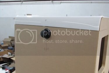
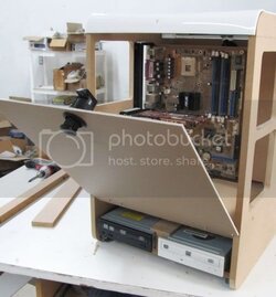
And installed them on with a nice latch on top and friction hinges at the bottom:

Panelinstalled1.jpg


The button latches catch on brackets I constructed from 1/2" delrin:

Panellatchcatch.jpg


To open the panels, you merely push the button, and the knob pops up:

Panelopen1.jpg


Twist the knob and the latch releases:

Panelopen2.jpg


Friction hinges will have the panels remain open to whatever angle you leave them.


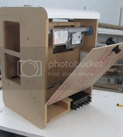
On the back, the panel opens up to allow access to the hard drives and power supply:

Panelopen3.jpg


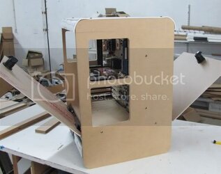
And with both panels open:

Panelopen4.jpg


Super easy access to your components!

I really love this latch and hinge system--I used the same setup on my Resilience project, altho paired with a nifty gas spring.


Here's a video with the panel system in action:

th_MVI_2769.jpg
 
Back