Hey Guys, been lurking on the forum for awhile and figured i'd upload my own TIM test. Most of the test i see are at room temperature ambients. This test was done in a chamber held at 118°F / 48°C. I would also like to study the long term affects on the TIMs in higher temperature environments.
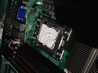
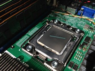
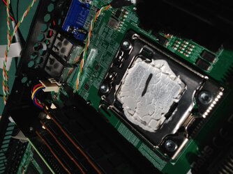
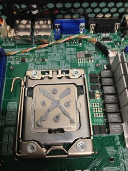
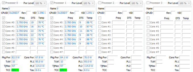
Processor: Intel E5-2440 2.4 GHz (dual)
Motherboard: Supermicro X9DBL-3
1U Server chassis
Passive cooling
Software: Proprietary software running CPU at 100% load and also stressing RAM.
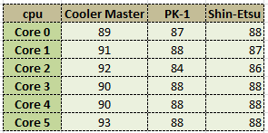
TIM's:
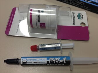
Prolima PK-1
Shin-Etsu X23-7762
Coolermaster ice fusion
The coolermaster stuff was laying around for awhile and probably way past its shelf life.
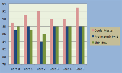
Temps (C°) were measured from the rear processor. TIM on the front processor remained unchanged for more accurate results of the rear processor. Core temps also fluctuated +/- 2-3°C. i didnt average the fluctuations, this was just for a quick test.

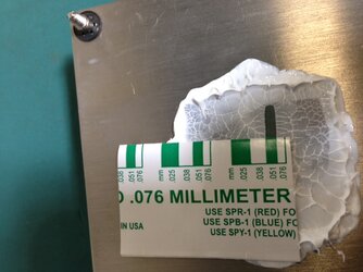
the shin-etsu stuff didnt spread very nicely, is this normal or could the package i bought be out of date?
Processor: Intel E5-2440 2.4 GHz (dual)
Motherboard: Supermicro X9DBL-3
1U Server chassis
Passive cooling
Software: Proprietary software running CPU at 100% load and also stressing RAM.
TIM's:
Prolima PK-1
Shin-Etsu X23-7762
Coolermaster ice fusion
The coolermaster stuff was laying around for awhile and probably way past its shelf life.
Temps (C°) were measured from the rear processor. TIM on the front processor remained unchanged for more accurate results of the rear processor. Core temps also fluctuated +/- 2-3°C. i didnt average the fluctuations, this was just for a quick test.
the shin-etsu stuff didnt spread very nicely, is this normal or could the package i bought be out of date?
Attachments
Last edited: