• Welcome to Overclockers Forums! Join us to reply in threads, receive reduced ads, and to customize your site experience!

VESA Wall Mount Project

Overclockers is supported by our readers. When you click a link to make a purchase, we may earn a commission. Learn More.

Navig

Senior Case Master
Joined
Dec 7, 2003
VESA Wall Mount Project


*** This is the complete build log in real time as I built this project. If you wish to skip right to my "Completed this Project" thread, click -->here<-- ***


Equation2.jpg


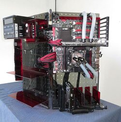
There are number of great Wall Mount PC mods out there. I guess I would define a Wall Mount mod as having the components all laid out flat on a flat surface, hung vertically, and on full display like a picture frame.

I did my own take on this type of mod in my project, the Vertical Benching Station. (I apologize, thanks to photobucket all my pics got screwed, so I am in the process of re-hosting all of them).


Motherboard%2Bside%2Bview%2Bbright%2Bsmall.jpg


This is actually my current personal gaming system. I sort of blended my own style of benching station with a wall mount mod--although instead of a wall, I used pegboard.


While I was building this project, a poster suggested I do a wall mount project specifically to go with a large screen TV.

I thought about different ways to combine a PC system and a big screen TV--On the one hand you could have a wall mounted PC just sort of hanging out behind or near a big screen TV. The big screen TV would just be separately mounted on a VESA wall mount bracket (VESA is the standard to make sure all your mounting screw holes line up between the back of your TV and the bracket). Just pulling from the web, something like this.

On the other hand, you can also build a mini or micro-ITX system into a component sized case, and just add it to your stack of components. Plenty of off-the-shelf cases for this like this from Silverstone.


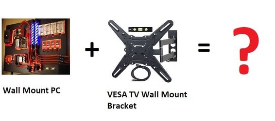
I decided to take it one step further and do something I’ve not seen before--why not build the big screen TV mount right into a computer case? Have the TV bracket integrated right into the case. That way you just mount the case to the wall. Then hang your TV from the case.


Wall Mount PC + VESA standard TV bracket = Navig’s Wall Mount VESA Project
 
Last edited:
VESA Wall Mount Project--Design Phase


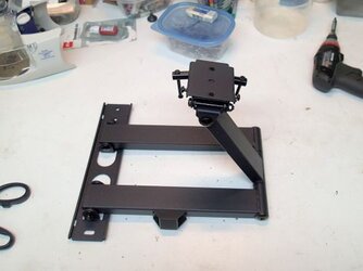
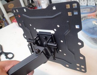
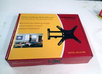
The first thing I did was purchase a VESA wall mount bracket. Didn’t feel like I needed to build my own and reinvent the wheel. So I picked up this unit from Amazon:
https://www.amazon.com/gp/product/B000WYVBR0/ref=oh_aui_detailpage_o01_s00?ie=UTF8&psc=1


VESA%2Bbracket1.jpg


VESA%2Bbracket2.jpg


VESA%2Bbracket4.jpg


Mounts simply--2 bolt holes. Has a lot of nice articulation. Mounts to the TV easily. Simply screw the TV bracket to the TV. Then hang the bracket on the end of the arm. Select your tilt angle. Tighten some screws.

However, even this simple design system is made from hefty steel, and weighs in at about 5 pounds. Add the weight of a big screen TV and we are talking some serious weight.

Your standard off the shelf panel style case is going to bend under this weight.
 
Design Phase, Continued


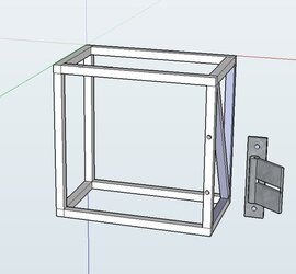
So here was my design, as planned with some Sketchup renderings.

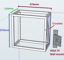
The main structure of the case would be a frame built from ¾” square tube aluminum.

.

Frame%2Bwith%2BVESA.jpg


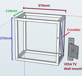
The TV bracket would then bolt to the frame. Notice I added an angled crossbar to help support the weight of the TV bracket and TV.


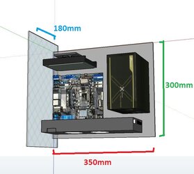
The PC components would then mount to a tray.
.
Motherboard%2Btray%2Bunit%2Blabeled1.jpg


I decided to go mini-ITX for my motherboard standard. This is probably a little controversial, as a single graphics card is currently not good enough to power a 4K resolution TV. On the other hand, I’ve always had nagging driver issues with multi-gpu setups, so I went for a single card solution.


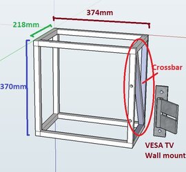
Once I laid out my components, I could create some measurements for dimensions. This motherboard tray and the components would occupy a 3D rectangle of 350mm by 300mm by 180mm. This space must fit within the frame, giving me the dimensions of my square tube frame:

Frame%2Bwith%2BVESA%2Blabeled.jpg


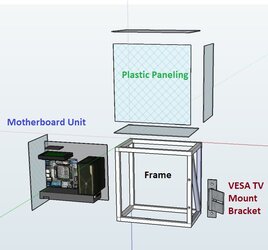
Here is a exploded diagram of the main components of my build:

Blowup1.jpg


You’ve got your square tube frame with VESA TV mount.

It will be clad with plastic paneling.

You’ve got your PC component tray.
 
Design Phase, Continued


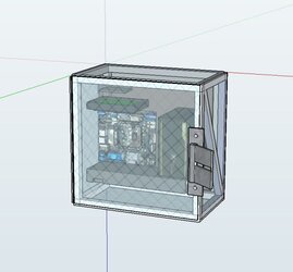
Assembled, it would look something like this:

Fully%2Bassembled%252C%2Bmobo%2Bin.jpg


All of this is going to be behind a big screen TV. But being the hardware nut kind of guy I am, I wanted my PC components accessible.


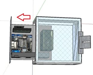
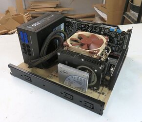
So my plan was to mount the PC component tray on industrial drawer slides. So when you need to access your components, you can slide out the entire PC component tray:

Mobo%2Bhalfway%2Barrow.jpg


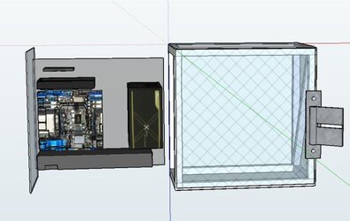
There is enough articulation in the TV mount I chose that you can just swing the TV to the side, and pull out the component tray:

Mobo%2Bfully%2Bout.jpg


There were a number of other details to work out--for example, how to mount the case to a wall. And also how to remote control your PC system, so as to not have to get off the couch to turn it on.

But overall, this was my design, so I got to building it!
 
Component Layout

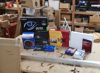
Next step was shopping.

Materials%2Bstack1.jpg

Purchased some stock materials--sheet plastic from Delviesplastics and ¾” (1/16” wall thickness) square tube aluminum from onlinemetals.

Purchased some PC components. I started with:
i7-6700k
Asus ROG Maximus VIII Impact
2x8gb G.skill TridentZ
Gigabyte Geforce GTX980
Intel 750 800gb
Corsair HX750
Zalman CNPS8900
Logisys PC Remote Start/Reset Controller


It’s one thing to design layouts on Sketchup, it’s a whole ‘nother thing to actually put components together. Particularly small form factor components--physical compatibility issues are practically inevitable.


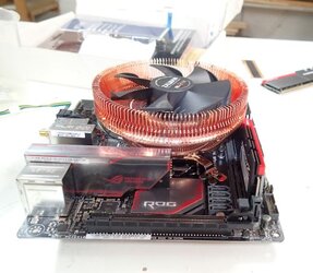
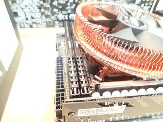
Which I ran into right away. The Zalman CNPS8900 performs awesome as a low-rise solution, but it would not fit with 2 sticks of TridentZ RAM:

RAM%2Bclearance1.jpg


Nor even with some lower rise 2x8gb Corsair Vengeance sticks:

Ram%2Bclearance.jpg


Ultimately I would change out for a Noctua NH-L12.


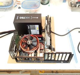
While this was on order, I recreated my planned layout, and found that it would work well:

Layout%2Bplan.jpg
 
Motherboard Tray mods


Time to dial in some subsystems in order to make this more finished.


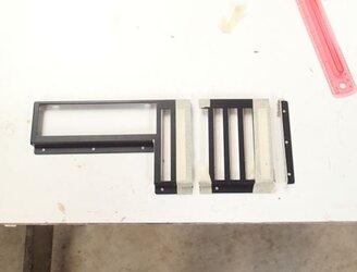
Chopped my PCI bracket down to a mini-itx size.


PCI%2Bbracket%2Bcut1.jpg

PCI%2Bbracket%2Bcut2.jpg


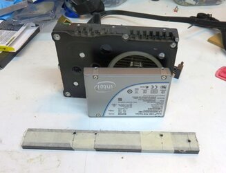
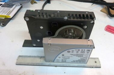
Started my hard drive mounting mechanism

I’m going with my DIY system, that I typically do for my DIY Benching station. Details on their construction are here.


Hard%2Bdrive%2Bcaddies.jpg

Hard%2Bdrive%2Bcaddies2.jpg


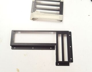
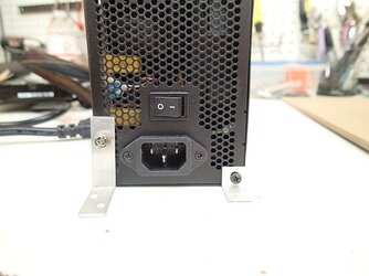
Couple of brackets to mount my power supply:


PSU%2Bbrackets.jpg


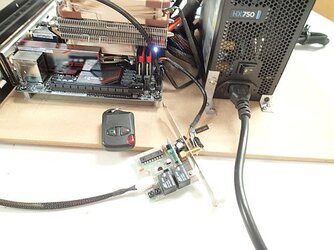
And put together and test my remote control system.

Purchased this Logisys remote system.

Out of the box, it has you drawing its power by interposing an adapter on the main 24 pin ATX power line. I’m not a real fan of that--it’s bulky, and it can affect the main power delivery to the whole motherboard.

So I modded the power-in line to the remote unit to plug into the free USB3 front panel connector. This whole computer is going behind the TV, so extra front panel USB headers are not really necessary.


Remote%2Bsystem%2Bfunctioning2.jpg


You can see the remote unit is being powered by tapping into a USB3 front panel header right next to the sticks of RAM.

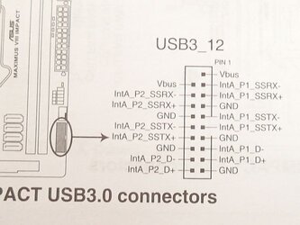
I’m tapping into Vbus and a GND:


Remote%2BUSB%2Bpinouts.jpg

5V power is maintained thru these lines so that you can have power to your USB ports while the system is off.
 
Motherboard Tray Construction


Enough of the planning and mock-up! Time to get constructin’.

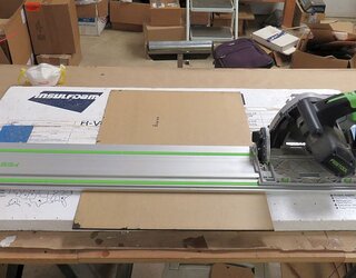
Mobo%2Btray%2Bcutting%2Bplastic.jpg

I’ll be using some ¼” transparent bronze acrylic for the main tray.


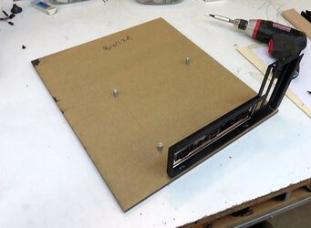
Started the layout with mounting the motherboard mounts and the PCI bracket.

Mobo%2Btray%2Bplanning%2Bholes2.jpg


Motherboard now mounts and fits nice:

Mobo%2Btray%2Bmounting%2Bmobo.jpg


Added the power supply mounts:

Mobo%2Btray%2Bmounting%2Bpsu.jpg


Mounted the industrial drawer slides:

Mobo%2Btray%2Bmounting%2Bslides.jpg
 
Motherboard Construction, Continued


Mounted my hard drives:

Mobo%2Btray%2Bhard%2Bdrives.jpg


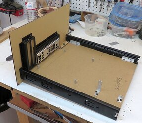
And here we have everything mounted:
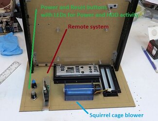
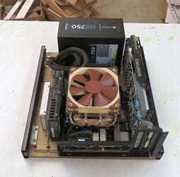
Mobo%2Btray%2Bassembled2.jpg


Mobo%2Btray%2Bassembled.jpg


And here are the slides in action:

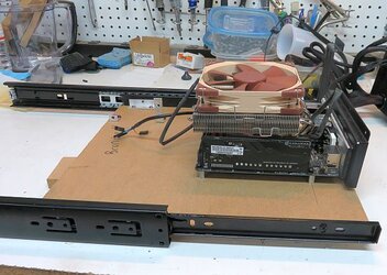
Mobo%2Btray%2Bslides2.jpg


There are even little latches that all you to completely disengage the slide, so that you can remove the tray entirely:

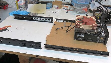
Mobo%2Btray%2Bslides3.jpg
 
Mobo Tray Construction, Continued


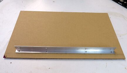
The next step was to put together the one side panel attached to the motherboard tray.

Mobo%2Btray%2Bupright%2Bpanel%2Bstart1.jpg

Its made of ⅛” transparent purple plastic mounted to a 90 degree aluminum bracket.


Mobo%2Btray%2Bupright%2Bpanel%2Bstart2.jpg


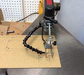
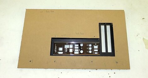
I cut out the hole for the PCI brackets and I/O panel with my scrollsaw:

Mobo%2Bupright%2Bcut1.jpg


Mobo%2Bupright%2Bcut2.jpg
 
Mobo Tray Construction, still Continued


I planned my layout for the the rest of the components that would be mounted to this panel:

Power and Reset buttons.
Exhaust fan.
Remote control system.


Mobo%2Bupright%2Blayout1%2Blabeled.jpg


Here's the plan:

Mobo%2Btray%2Bupright%2Blayout%2Bplan.jpg


Cut and mounted:
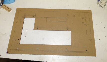
Mobo%2Btray%2Bupright%2Bmounted2.jpg


Mobo%2Btray%2Bupright%2Bmounted.jpg
 
Motherboard Tray, finalizing fit


As I threw my components back onto my tray to make sure everything fits, I realized that my plan is for this whole tray to be mounted vertically. So, the 2 edge mounts for the power supply were not going to be sufficient to hold down the power supply.

I have done floating power supplies in the past, so this was my simple and very effective solution.


Power%2Bsupply%2Bhold-down1.jpg

I mounted and cut to length some 6-32 threaded aluminum rod.


Made a hold-down bar from ½” aluminum trim (I’ve also added foam padding underneath so as to not scratch the psu) and mounted it with some nuts.

Power%2Bsupply%2Bhold-down5.jpg
 
Frame construction


Now it was time to shift focus and start constructing my frame.

Once again, here was my plan.


Frame%2Bwith%2BVESA%2Blabeled.jpg


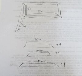
Based on these numbers, I generated my cut list.

Frame%2Bcutlist.jpg


I have done a number of aluminum square tube frames in the past. My plan was to make a simple rectangle frame with each corner meeting with a double miter.

Double%2Bmiter.jpg


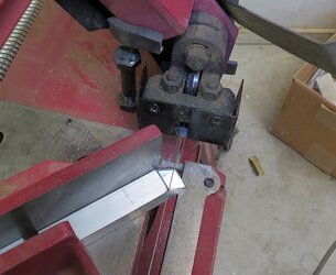
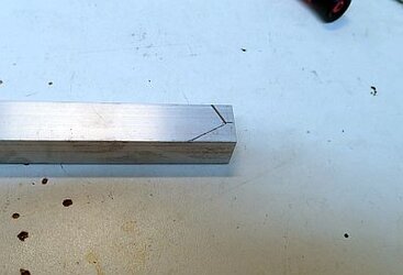
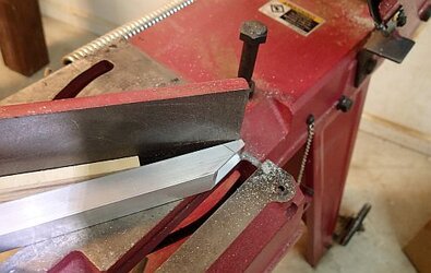
I cut my double miters on a bandsaw. After making the first 45 degree cut, I turn the square tube and make a second 45 degree cut so that is comes to a point with a double miter.

Frame%2Bcompound%2Bcut.jpg


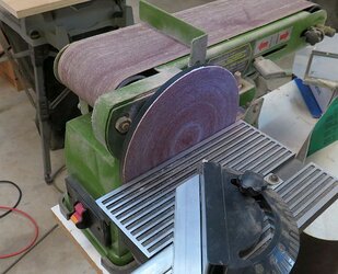
Fine-tuned with a sanding disk.

Frame%2Bcut%2Bdisk%2Bsander.jpg


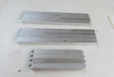
And here I’ve got my whole set of bars, double mitered on both sides.

Frame%2Bcutlist%2Bcomplete.jpg
 
Frame Construction, continued


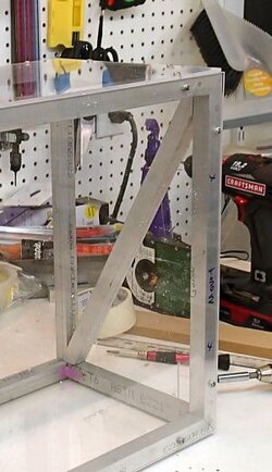
Time to make this crossbar that provides extra support behind the TV bracket.

Crossbar%2Bframe%2Bdiagram.jpg


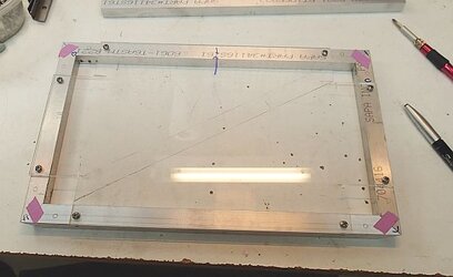
To fabricate this, I first cut some spare plastic to hold this panel together.

Crossbar%2Bplan1.jpg


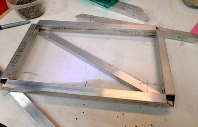
Then I laid a length of square tube and marked my angles to cut.

Crossbar%2Bplan2.jpg


Crossbar%2Bplan3.jpg


Cut’em on my band saw.


Crossbar%2Bplan4.jpg


Crossbar%2Bplan5.jpg

Perfect fit, makes it super sturdy.
 
Frame Assembly


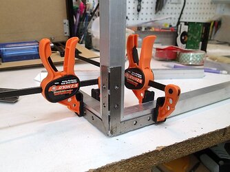
At first my plan was to connect my frame with these corner brackets I had from previous projects.


Frame%2Bcorner%2Bbracket.jpg


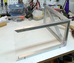
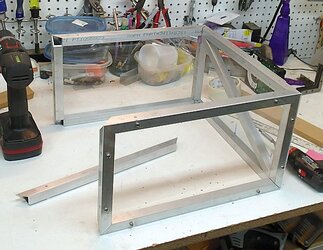
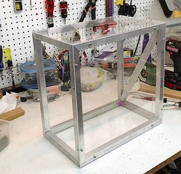
But after making the temporary jig for my previous step of making the crossbar, I went ahead and made temporary plastic panels to hold the entire frame together.


Frame%2Bplastic1.jpg


Frame%2Bplastic2.jpg


Frame%2Bplastic%2B3.jpg


Now it’s really starting to look like something!
 
Navig, question for you. Why only one crossbar, is it because you felt that it only needed addition bracing where it was going to be attached to the wall?
 
Back