• Welcome to Overclockers Forums! Join us to reply in threads, receive reduced ads, and to customize your site experience!

Wiring LEDs to a fan's PCB

Overclockers is supported by our readers. When you click a link to make a purchase, we may earn a commission. Learn More.

skorpien

Member
Joined
May 9, 2011
Location
Alberta, Canada
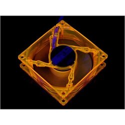
I've got a few fans I've purchased on eBay, discontinued Cooler Master UV Silent 120mm fans, and I'm thinking of wiring UV LEDs to the fans' PCBs.

The frame itself has four holes where it looks like LEDs would fit (probably used same mold from an LED model) and the PCB has four spots where it looks like one could solder the LED wires.

Does anybody know if it's possible to convert these fans to LED fans?

Also, do you know the voltages of the terminals? I can figure that part out myself (I have a digital multi-meter) but if you know that would be greatly appreciated :)

I could use an external source to power the LEDs, but as the holes are in the arms of the hub (not on the round frame like a lot of LED fans today), I can't figure out how I could make the wires look good and keep them out of the way.

Hopefully I was clear in my explanation.

Thanks in advance!
 
For powering them, you can run them off your PSU, just find an adapter from a spare fan and splice it in. Red is red, black is black, positives and negatives dont change lol.
 
I've got a few fans I've purchased on eBay, discontinued Cooler Master UV Silent 120mm fans, and I'm thinking of wiring UV LEDs to the fans' PCBs.

The frame itself has four holes where it looks like LEDs would fit (probably used same mold from an LED model) and the PCB has four spots where it looks like one could solder the LED wires.

Does anybody know if it's possible to convert these fans to LED fans?

Also, do you know the voltages of the terminals? I can figure that part out myself (I have a digital multi-meter) but if you know that would be greatly appreciated :)

I could use an external source to power the LEDs, but as the holes are in the arms of the hub (not on the round frame like a lot of LED fans today), I can't figure out how I could make the wires look good and keep them out of the way.

Hopefully I was clear in my explanation.

Thanks in advance!
Can you post a pic?
 
Yeah, using the PSU would be simpler but because of where the LED holes are located, I cant figure out how to make the wires look good. I don't want to have to drill any additional holes, and as the fan is translucent, any mess or wires will be visible.

I can take a picture when I get home, but I found one online of an 80mm fan that demonstrates where the LED holes are. It's not clearly visible in the picture, but under the sticker on the fan hub there are four large holes exposing the PCB. There are 2-3 soldering terminals in each hole that look like they could have been used to power the LEDs in each arm of the hub on a different model (I'm thinking CM recycled the mould for the frame and possibly the PCB design of another fan that did have LEDs). The fan's header is fed through one of these holes and soldered to the terminals in that hole.

41aAiBEGE6L._SS500_.jpg
 
It seems that despite using the same frame and PCB as fans with LEDs, Cooler Master didn't fully wire it for LED leads.

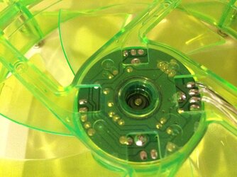
Here are a couple of pics of the back of the fan. You can see where the LED holes are situated in the frame and where it looks like LEDs could be soldered to the PCB.
fan1.JPG

fan2.JPG

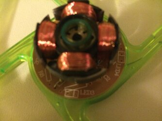
However, looking at the front of the PCB shows that even though there are labels for the LED leads, there are no wires going to those holes.
fan3.JPG

And unfortunately, a quick test with my digital multimeter shows that the terminals are indeed unpowered.

Looks like I'd need to either use the 12V and ground lines coming from the PSU and use some resistors (would probably look quite unsightly) or I'll just have to figure out a way to hide longer wires and connect them to a Bitspower LED hub which has 3.3V terminals (so no resistors required).

Thank you all for your help :)

Edit: Come to think of it, that first option is kind of out of the question. I couldn't figure a way to remove the PCB from the housing (without breaking it of course), so soldering so close to the plastic might not be so easy.
 
You could bury the resistors in those cross beams. Just solder on the pad for power and GND and break it out to each of the cross supports.
 
I was thinking about doing that. I'd feel much better if I could pry the PCB from the housing so I don't accidentally burn/melt the plastic.

I couldn't figure out how to completely disassemble it without having to break the fan. It's not a twist off style like my Gentle Typhoons.

Is there a trick to taking fans like these apart?
 
An LED bar? On the fans or in the case directed at them? Sorry, I'm having trouble picturing what you meant.

I'd like for the blades to be lit up if that's possible. I worry that if the LEDs are too far from the fans, the UV effect wouldn't be as noticeable.
 
View attachment 137412

And unfortunately, a quick test with my digital multimeter shows that the terminals are indeed unpowered.

Looks like I'd need to either use the 12V and ground lines coming from the PSU and use some resistors (would probably look quite unsightly) or I'll just have to figure out a way to hide longer wires and connect them to a Bitspower LED hub which has 3.3V terminals (so no resistors required).

Thank you all for your help :)

Edit: Come to think of it, that first option is kind of out of the question. I couldn't figure a way to remove the PCB from the housing (without breaking it of course), so soldering so close to the plastic might not be so easy.

You can just run the resistors on-board. You'll need to figure out a way to pull the PCB out, but if you look at the PCB layout, the hole with the long box next to it seems to be right for a resistor, and if I'm reading the PCB right (it's hard to orient from front-back pics with stuff obscured), the resistors should just be in serial with the LEDs. If you pull the PCB and post good front/back pics of it, I can give you a better idea of what exactly you need to do.

Credentials: I'm 15 credit hours from graduating with a degree in electrical engineering, and I've been fiddling with stuff for a long time.

EDIT: Don't destroy anything on my account. If you can't get the stator out, just go with a different solution.

Thanks for your help, m0r7if3r, and I apologize for the poor quality of the pictures.

I've tried taking the PCB out but I'm afraid that short of taking a hammer to it, I'll never get it to budge. I'm beginning to think that they used a strong adhesive to hold it in place, or that I'm missing something that needs to be undone before it can come loose. I've tried contacting Cooler Master, but they understandably don't support any attempts at modding their fans.

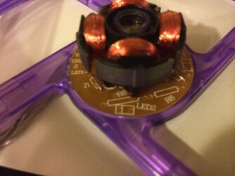
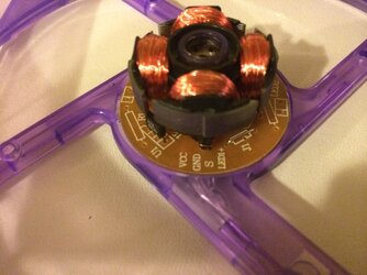
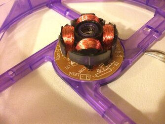
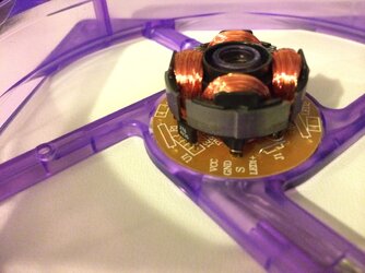
I tried in vain last night to get the PCB out on a purple fan that I had lying unused from another build, but the best I could do was get a picture of the PCB from four sides at an angle so you can see the writing beneath the stator.

fanPCB2.JPG

fanPCB3.JPG

fanPCB4.JPG

fanPCB5.JPG
 
I realize now that soldering resistors and wiring the LEDs into the PCB is going to be next to impossible.

My main concern was where the holes in the housing are located. Running wires to the 4 LEDs, I'm worried that it will impede the fans' abilities to be placed side by side or flush to the radiator.

I may have to drill holes to pass the wires through regardless. I know I said I wanted to avoid drilling holes, but at least the holes for the wires don't require as much precision as if I were to drill holes for LEDs around the edge of the frame (as per this guide).
 
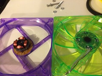
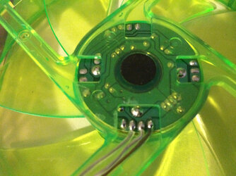
Hi m0r7if3r. From what I can tell, the U1 isn't what's running the 12V and ground in. I've taken two pics of the fans side by side with the fan headers aligned at the bottom, and each fan separately again with the fan headers aligned at the bottom of the pictures.

IMG_1054.JPG

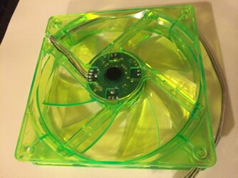
The 12V and ground wires are attached to the VDC, GND and S (12V, ground, RPM sensor).

The U1 corresponds to the four terminal points to the right of the fan header terminals on the back of the PCB (following green fan picture). The fan header terminals on the back of the PCB are, from left to right, RPM sensor, ground and 12V.

IMG_1055.JPG

IMG_1056.JPG

I'm wondering if figuring this out is even worth it though, considering I have no idea how to remove the PCB without breaking the fan.
 
Sorry for the delay, I've been all over the place today. This should be fairly simple, if you want to do it. How I would go about it would be to put in the necessary resistors on top of the PCB (on the yellow side) without using the through-holes that are blocked off. From there you can just run wires out to the LEDs and viola. I can spec the resistors to whatever LEDs you choose, just post the specs of the LEDs you're using.

I'm having a hard time tracing the 12v in. I think it might already run to all of the LEDs, but I can't quite tell. Can you follow the raised line (I believe it's the dark green one, but run your finger over it and confirm that that's the raised part) that comes off the 12v wire (it's the rightmost in the picture of the green fan) and see if it connects to one each of the LED pads or not?

Alternatively, if you don't mind it being a bit messier, you can just cut the traces around the LED pads so they don't conduct and then run directly off the 12v supply.

There will be room within the housing for some small resistors, right?
 
No worries, I've been somewhat delayed in my replies as well :) I really do appreciate your help.

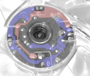
I think I've managed to trace the 12V in and ground on the PCBs. The red is the 12V and the blue is the ground.

circuittrace.jpg

It looks like the 12V doesn't run to the LEDs themselves, but to the rectangles on the PCB that are designed to hold the resistors. The LEDs are connected to the opposite end of the resistors, and the ground is just the ground. I hope that makes sense?

I think there should be room for resistors under the stator. The fan already uses one resistor for something, and that lies close to the PCB and out of the way.

This would be a whole lot easier if I could just remove the PCB. How much force is usually required to pry them apart?

Edit: Forgot the specs of the LEDs. According to the eBay listing, the UV LEDs' forward voltage is Min: 2.8V Typical: 3.2V Max: 3.8V and 30mA

Using 3.3V and 30mA with a 12V source, I used an online resistor calculator which said that a resistor of 330 ohms, 1/2W is what I'd need for each LED.
 
Last edited:
Resistor calculations:

Code:
V=IR
R=V/I
R=(V[sub]source[/sub]-V[sub]LED[/sub])/I
R=(12-3.2)/30E-3
R=293

270, 300, and 330 ohm resistors are all standard values, but 330 and 270 are more common in my experience. Any of those three should be fine.

You'll want one resistor per LED (LEDs go in parallel as a matter of good design practice). Solder the resistor between the LED pad and +12V. Solder some wire to the same pad as the resistor, run it out to your LED (make sure you get the polarity right on the LED) and run the other wire back to ground. Don't be afraid to stick the wires down to the PCB.

Protip: leave as little of the resistor leads exposed as possible, they're a shorting hazard.

If you're not sure how do to any of that let me know.

In terms of getting the board out, I'm not sure. I think I've done it before, but I couldn't tell you when or how...also I bet it varies by the fan, but that's just speculation.
 
Thanks m0r7if3r. I'll see what I can do with it all. I was thinking of using heatshrink on the resistors after soldering them to cover up any exposed bits. I'll have to wait a bit for the resistors if I'm ordering them online, so that will give me some time to try and see if I can get the PCBs out.

I really do appreciate the help. Even if nothing comes of this (if I just wire the LEDs using an external source), it's taught me a lot about tracing PCBs and making sense of them (that's assuming my colour illustration was accurate :p ) Thanks!
 
Back