• Welcome to Overclockers Forums! Join us to reply in threads, receive reduced ads, and to customize your site experience!

FEATURED Building PWM Controller for 4 wires PWM fan

Overclockers is supported by our readers. When you click a link to make a purchase, we may earn a commission. Learn More.
I hate being a newbie. I'd like to build a PWM controller using some digital means to increase the fan speed (instead of using a pot). I've read thru some of this thread (dang...) but out of the 28 pages where can I start?

I have 2 Nidec BetaV TA3500DC 12V 2.3A PWM fans. They came out of a Dell XPS Gen4 tower. Any ideas where I can start reading (other than page 1)?
Thanks

Well, unfortunately if the two posts before yours don't ring any bells, I would recommend starting at page one.. honestly I know it's daunting but I did myself when it was 26 pages, and it's worth the read if your doing something like this for the first time yourself. Take a few days, and follow the thread, I think you will appreciate it more ;)

Also, welcome to the forums ;)
 
Thanks for the feedback.

@repilce, I think you are right. Even though starting from the beginning may take time, but it is easier to follow having read the background.

@Bobnova, I tried to pick up in the middle of the thread, but got lost. (Jumping in at post 836 or 775)

So, I'll go do my homework and come back (I hope) a bit more educated.

Thanks again...
 
Last edited:
As for the control method, the original idea was to get data via lcdsmarte through the USB port. I would send core temp's, GPU temps, and board/northbridge temps.<SNIP>

This sounds very close to what I want to have eventualy.
When I finally have the time to focus on it again. Very nice & good-luck! :thup:
 
Last edited:
@ inVain, that controller you sent Bing is gorgeous. I think the next case build I do, I will go that route.
 
@brutal
the controller which I sent to Bing actually is the best performer that I've ever build until today,

but I planned to build something more convenient to be placed inside the case and applied the kick start that Bing has added for the controller in the next few day...

I've got the rough plan on mind, and will try to share my progress here ;)
 
Awesome. It was beautiful.

Mine is not visible from the outside as I am using the rheostat on my sunbeam controller. Unfortunately I killed it to do this, so I am unable to use it on my other fans.

I would like to fabricate something like you have constructed and then purchase another sunbeam for my non-pwm fans.
 
as for the additional kick start, as mentioned by Bing on this post -> here

would someone please, be so kind to recheck my connections (especially you, Bing :D)...

the schematic was intended for IC#1 on the 0-100% version:

vgaczekp3mnqgys08w0o.jpg


@brutal, if you managed to fabricate something, please let me see it here :)

and here's the main ingredients for my next controller build:

ihxlkyrzvnny783bc6cr.jpg


the unemployed GFX holder (thx to cooler master :D) will be used as the housing for the main PCB, the PCI cover will be used to mount the pots (I can't think any better idea)


as for the "cool" factor, let's have a pairs of DIY neon to light up the night :D

2csmn7zw0bneb910h1v7.jpg


the "neon" was made of two blue 3mm leds and a straw :sly:


lets have a quick snap shot of this matrix FX :comp:

gge6ltccmfg8cuvp4xhi.jpg


not too shabby for a sub $1 part ain't it:D
 
inVain, the schematic looks fine. Great, I guess we're expecting to see this kick-start video in action really soon. :p


as for the "cool" factor, let's have a pairs of DIY neon to light up the night :D

2csmn7zw0bneb910h1v7.jpg


the "neon" was made of two blue 3mm leds and a straw :sly:

Really love this simple but effective idea using straw to make the backlight :thup:. I've done same thing in the past but it was using a half transparent glue stick that is used in hot glue gun for lighting up a small box using high power led.
 
Last edited:
thx for clarify the schematic, Bing :)

the progress is really slow lately, I don't even have test the ULDO controller properly :(
but hope I can work on something real soon :salute:

glad that you like the straw-led idea.
that "glue stick neon" sounds even better ;)
 
@Bing: Really quick question on the kick start schematic; is that r7 100k? It only says 100.

Hey Gregory, :welcome: to Ocf !

Yep, its plain 100 Ohm (one hundred), not 100K.

At resistor's value, the "K" suffix stands for Kilo or x1000, eg 47K equal to 47000 Ohm.
 
Hi guys,
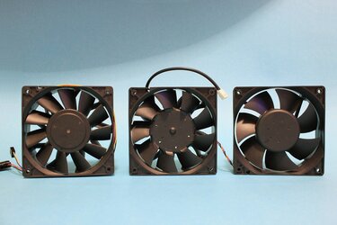
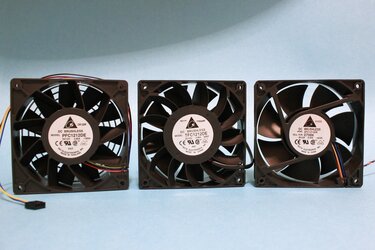
showing you some DELTA fans right here. Left hand side the PFC1212DE - 4.8A, middle the TFC1212DE - 3.90A and right hand side AFC1212DE - 3.0A.

img_567037rc.jpg
img_566927nm.jpg

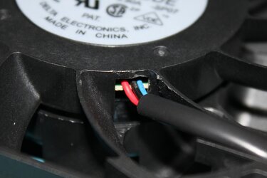
The TFC is my oldest and now while reading this thread i wonder if it has to be PWM Fan? A detailed picture pionts out thet it is manipulated by the seller.

img_5675y7cg.jpg

I bought it on ebay :-( Is there a chance to add a PWM-wire to bring PWM option back to service or is it dead? One can find these less equipped TFC1212DE on ebay here, correct equiped ones look like here. What do you think? Sorry for using this thread, but maybe some pictures will excuse this :)
 
nothor,
that's really strange....
your TFC doesn't look like PWM fan at all, like it SHOULD be :confused:

are you sure it's not a refurbished one?
coz I think the one who sell it to you was messed up with this fan :sly:
 
Hi inVain,

i've decided to disassemble the TFC1212DE, cause it's useless to me without PWM control.
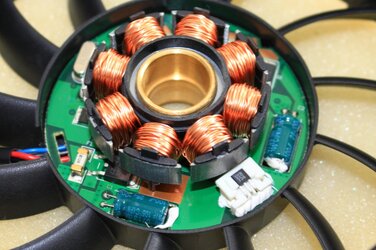
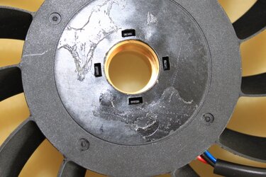
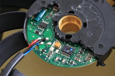
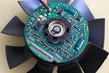
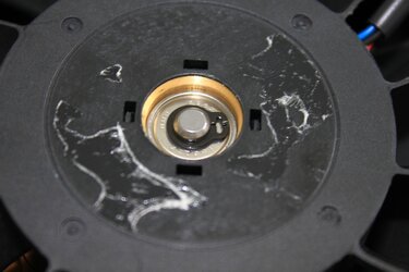
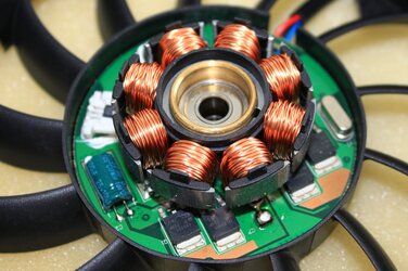
But now i had to stop. I don#t now how to continue. Can't move out the PCB. The wires are soldered on the back side of it, if you're looking onto the stator. I think the solution is to loose the clips on the back (see fourth pic). But it needs brutality to unclench the clips. I'm not sure if the fan will survive. :-/ Never the less it looks completely like new, i can not imagine why it has to be refurbished, looks like factory new.
delta_tfc1212de_nabe01lc1m.jpg
Stator:
delta_tfc1212de_statorfd2k.jpg
delta_tfc1212de_stator4ew4.jpg
Clips to loose:
delta_tfc1212de_nabe026dhs.jpg
I think PWM-control circuit is located on the back side of the PCB.

edit:
Yes it is, and it have had to be a PWM-Fan, but the wire was cracked out. RIP
delta_tfc1212de_pcb1pe0o.jpg
delta_tfc1212de_pcb21e2p.jpg
 
Last edited:
nooooo.......you've killed the delta :cry: :rain:

actually you can take off that clip with a tiny screw driver (I done it to take off the "o-ring" that lock the spring on the HSF nut)

sorry, I never thought that you would mutilate your delta...
I've should give you the link to this thread before -> click

but seeing the gut of that fan makes me :drool:

:D
 
Taking off the "O-ring" was no problem, the Rotor with the blades and the two bearings fell easily out. On that last picture i fixed it again, just for the pic. But i found no way to loosen up the board to have a backside view where the wires are soldered on. In the thread you linked the fanframe is also cracked to access the wire terminal on the board. But not i woul know where to drill a hole to access the wire-soldering-spots. Perhaps i makes you happiere if you think about that fan was handicapped even before my vandalism :-/ I will by a new one with full funktionality to play with. :)

But you're totally right with showing the right thread where i have had to post my problem in.
 
Last edited:
Northor, really sorry to hear you've lost that fine fan. :cry:

Also yes, that fan is a pwm type, I have two of this exact model and both of mine have the 4 wires and from the pic, looks like the pwm wire was pulled and snapped at the pcb solder point which is almost impossible to fix without dismantling the whole fan and its very difficult to do without destorying it. :bang head

Here, shot of my TFC1212DE, look at the wires, it has 4.

picture.php


PS : Would you please resize those pics, may be similar as mine cause yours are way too big.


.
 
Last edited:
Thanks bing, i've ordered another one with 4 wires at ebay for $10. I think it'll.
What to do now with the parts of the other one, the PCB, stator and rotor is still undamaged, only the frame is destrojed. But i do not know how to fix the PCB and parts in another frame.

PS: i'll try to resize the pics.
 
Bing: Could I use the controller design to drive a mosfet which would be hooked up to a normal non-pwm fan? This would allow non-pwm fans to have pwm control, wouldn't it?
 
Back