• Welcome to Overclockers Forums! Join us to reply in threads, receive reduced ads, and to customize your site experience!

FEATURED Building PWM Controller for 4 wires PWM fan

Overclockers is supported by our readers. When you click a link to make a purchase, we may earn a commission. Learn More.
I've been following this thread for a while. I thought it was as the title said, building a PWM controller for 4-wire fans. A lot of good progress and schematics here to do the trick!

I thought I would add this to the thread list, just as an FYI in case someone wanted to use the PWM controller on their mobo (CPU Fan, or case fans). In my case, I have an ESA board that has 5 PWM outputs (up to 5A each). :O

And in my case, I needed a few high speed 140mm PWM fans. Problem is, they don't exist. So, I'm gathering a few 3-pin fans... And use this converter:

http://www.paqt.co.uk/store/index.php?act=viewProd&productId=5

Max output is 500mA (0.5 A) though, so i have to be careful.
 
Would you mind posting a pic of the converter board? Ideally both sides.

I'd love to see what they came up with.
 
Would you mind posting a pic of the converter board? Ideally both sides.

I'd love to see what they came up with.

Not pics of the board itself, but I'm sure this will hold you over for a while until someone does post full res pics of the thing.

Datashee: http://www.paqt.co.uk/docs/PaQ_PWM.pdf There is a better sized pic in there that you can look at and make out most of the components. The text is just marketing jibber-jabber.
 
Iiiiiiinnteresting, thanks seebs!. I see no caps worth mentioning. I also see no inductors worth mentioning.
Looks like a fairly creative use of transistors. Actually fairly similar in that aspect to what the Rasurbo case I reviewed used for it's fan controllers, though they capped out at 200ma (laughable).

I'd still like to see the back side though, and ideally know the markings on the 3 legged characters.
I need to find myself a PNP mosfet (like off this blown to hell ud3p mobo....) and I think I can make a buck circuit.


Also: Who advertises with a perfboard prototype?
 
Bing: Could I use the controller design to drive a mosfet which would be hooked up to a normal non-pwm fan? This would allow non-pwm fans to have pwm control, wouldn't it?

Yes, its possible and if you build this controller solely just to drive the mosfet to be connected to non pwm, I think its a bit excessive since you don't need this kind of complexity. There are other simpler approach, or you could just use the original Nidec circuit using single 555 and few discrete components and a mosfet.

But if you want a single controller that can drive bunch of 4 wires pwm fans, "AND" also drive a mosfet for the non pwm fan, its possible to tweak this circuit to do that.

Just fyi, normal non pwm fan is better driven using voltage rather than crude mthod pwm-ing it's power, check my post #814 -> HERE, where I posted the concern using this method.


I've been following this thread for a while. I thought it was as the title said, building a PWM controller for 4-wire fans. A lot of good progress and schematics here to do the trick!

I thought I would add this to the thread list, just as an FYI in case someone wanted to use the PWM controller on their mobo (CPU Fan, or case fans). In my case, I have an ESA board that has 5 PWM outputs (up to 5A each). :O

And in my case, I needed a few high speed 140mm PWM fans. Problem is, they don't exist. So, I'm gathering a few 3-pin fans... And use this converter:

http://www.paqt.co.uk/store/index.php?act=viewProd&productId=5

Max output is 500mA (0.5 A) though, so i have to be careful.
I'm aware of this gadget too, too bad it's power rating is too low and also there is no detail explanation on it's adjustment feature, imo ideally it should provide flexible adjustment like I pointed it HERE, fyi that thread owner is trying to build such circuit, but there is no update or news anymore on the progress.


.
 
I have a functioning boost converter, next up is a buck converter, after that is a high amp buck converter :D
I need to dig up some TTL level PNP mosfets to play with for the buck though I think.
 
Hello, i'm subscribed to this thread since several weeks, so now i want to have a PWM-Controller too. :cool: But i don't really know the partlist and the circuit plan. Especially the exact item part number is a ridle to me. :confused: What i have is 16 years of soldering experience, equipment and a lot of PWM-Fans waiting for beeing controlled. Especially the controller with the kick start option seems to be very interesting.
Is there any list to find online or in this forum?


Everything you need is on this very same thread. You just needed to go back to the start of it.

Circuit Diagrams & Parts Lists: Post #25
 
I have a functioning boost converter, next up is a buck converter, after that is a high amp buck converter :D
I need to dig up some TTL level PNP mosfets to play with for the buck though I think.

Keep us updated Ed ! Really eager to see it works. :thup:


Hello, i'm subscribed to this thread since several weeks, so now i want to have a PWM-Controller too. :cool: But i don't really know the partlist and the circuit plan. Especially the exact item part number is a ridle to me. :confused: What i have is 16 years of soldering experience, equipment and a lot of PWM-Fans waiting for beeing controlled. Especially the controller with the kick start option seems to be very interesting.
Is there any list to find online or in this forum?


Aha ... there you go, with your impressive pwm delta monsters collection there, I think this is the right time.

Now, back to your question, which part you don't understand, the circuit actually is quite simple, while the components all you need is just write down a list of needed components from the schematic and go shopping.

Not sure in Germany, how do you buy these kind of components ? Do you shop at the store or thru online shopping ? At store definitely is easier since the shop keeper might help you.

Keep us informed on your progress.
 
bing @ xXSebaSXx:

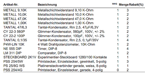
Thank you for helping. The List of components is complete. But my first try to order it on "conrad.de", a popular electronic components dealer in germany with online shop also as local stores (only 3 km from here) offers capacitors and resistors with 1k Ohm etc. with 50 V and up. Does it matter, doesn't they had to be all 10V models? Can i use a 500 V rated voltage Resistor? In your helpful schematic you do not have any info to the rated voltage of the resistors and capacitors exept the first one C5 in your 0%-100%-Schematic, so i think it doesn't matter, right?

The capacitors can be 10V or 100V or whatever volts you prefer; as long as the capacitance (f) is correct it doesn't matter. The only difference is that the higher voltage capacitors will start to get more expensive. :D

For the resistors; as long as they are rated for the Ohms that the circuit calls for; the Watts rating can be whatever you like... I used all 1/2W resistors on my circuit and could have easily done with 1/4W resistors or even 1/8W. Again as long as the resistance is the one that the circuit calls for; the rest is pretty much up to you. :D
 
You can use capacitors with a higher voltage rating, not an issue.
Lower voltage rating isn't an especially good idea.
 
Nothor, about the cap, since these circuits either versions will be working close 12 volt even they need only at 5V, my suggestion is just buy cap with 16 volt rating, that is enough. Although higher voltage rating than 16 volt is fine too, its just they will a bit bigger and probably will more expensive, not much though and sometimes at certain places they cost the same as well.

Resistor, any type either carbon (cheapest) or metal film (more expensive) is ok too, and for the wattage, either 1/8 watt , 1/4 watt or 1/2 watt is ok, these circuit are not too demanding.

The most important thing to remember is "BUY MORE SETS" :D so you will have enough spare just in case they're toasted or even dead on arrival, this is normal especially for those cheap IC like NE556 or LM311. :(

Also other minor parts like wires or cables and connectors for those fans and power supply connection.

Finally, I highly recommending you to buy breadboard, so it will easier to trouble shoot if its not working for the 1st time, soldered components are really hard to trouble shoot and messy too.
 
Thank you very much, i've placed my order today on reichelt.de. For bringing pictures up to this thread: ;-)
listeikfi.png
 
nothor,
if it possible, maybe you want to get something with higher voltage (like 10v or 16v) instead of the 47uF / 6.3v tantalum.

tantalum is good, but the electrolyte was also fine if you can't find higher voltage tantalum :)
 
Nothor, your components selection is fine, but as inVain pointed out, just take extra precaution in powering it, cause that tantalum capacitor is rated for 6.3 volt, so if you accidentally connect the circuit to 12 volt rail which supposed to be at 5 volt, the 12 voltage will destroy it instantly.

Actually you don't need tantalum type since it more expensive, an ordinary cheap electrolytic type is fine too, and if you're going to buy again, make sure they're rated minimum at 16 volt or higher.

The circuit it self is capable taking 12 volt easily but there is a possibility that the fan's pwm line might not, but again, just make sure you check & re-check on the power connection that its connected to 5 volt (red wire at molex) instead of 12 volt (yellow wire) before you power it up.
 
running out of soldering tin, while got all the mood to gripping the soldering iron...:bang head

so I thought I'll just share the pics :D

3l1tmcisydx2hcdz7r6a.jpg


and bing,
here's a tribute to you; a dip switch (hope I'm setting it right :attn:)

z28dblrvn8ihbuzsf8kn.jpg
 
That looks great inVain. What is the switch for? And what is the heatsink cooling?
I'm awaiting the parts to start bulding up my first pwm control circuit. Today i've followed your advice and got the firt part from the shop nearby, a 47µF/10V capacitor :)
 
thanks nothor :)

Actually, this is a dual controller module...
the heatsink is for the analog line, it's cooling an LM317 chip. And it supposed to control this fan:

fhyo675na7hlvf5lomrk.jpg


PAPST 4112N/31HHA,
it's a 4 wire fan, but instead having PWM as its speed controller, this fan need a linear input 0-10v to control its speed.
This is a solid fan, and I want to use it inside my case, so I build the controller.


As for the PWM controller, I'm planning to build the 0-100% version with the "kick arse version :cool:" (the kick start actually :lol)

The switch is for bypassing the kick-start function. Just in case with my current Delta PFC with the softstart feature, so, whenever I need to swtich off the kick-start feature. All I have to do is just switch the switch position :D


And great that you came up with the higher rating voltage capacitor, just make sure that you feed your PWM controller from the 5v rails of your PSU (the red cable).

Keep us updated with your project, will you....

cheers :)
 
Thats great, inVain. Hope you'll get this PAPST fan up to full satisfying function.

See what i found at nidec america. Do they adept the need of publishing adequate pwm-support information from this thread? :sly:
 
Last edited:
Back