• Welcome to Overclockers Forums! Join us to reply in threads, receive reduced ads, and to customize your site experience!

DIY Fan Controller for PWM Fans

Overclockers is supported by our readers. When you click a link to make a purchase, we may earn a commission. Learn More.
I've just recalled a regular diode like the ones we use here have limited frequency capability. PWM signal is supposed to be 25 kHz. Don't you guys think the two diodes in the project should be schottky diodes?

For the frequency used with PWM, silicon diodes are fine. I looked at that video and that guy is wrong on current flow in the diodes, it's from cathode to anode against the arrow , NOT anode to cathode with the arrow.
This got started way back in the 1800's when batteries were fist made, people thought that current went from + to -, when vacuum tubes came about, they found out that it went from - to +, but some people did not want to change their way of thinking, so we now have Conventional current flow (+ to -) and Real current flow (- to +).
IIRC, he has put a caption correcting that bit.

OK, I've been thinking (as I don't have access to an oscilloscope) what could be wrong. And the only thing I came up with is - may I use common ground for 12 V power supply for the fans and my PWM circuit? Currently I do.
EDIT:
I think I have found an answer in the other thread!
A guy asks:
Has anyone hooked the 2-98% circuit on an oscilloscope? I've been taking some frequency measurements on it and I'm getting a variance between 1.2khz and as high as 151Khz..

http://www.overclockers.com/forums/...ires-PWM-fan?p=7149070&viewfull=1#post7149070
From subsequent posts I have read the circuit is far from perfect and that it's not unlikely that some fans will misbehave with it.
Recommended circuit:
http://www.overclockers.com/forums/...ires-PWM-fan?p=7239325&viewfull=1#post7239325
(with dead links)

Keyword used: Oscilloscope

In conclusion, I see no point pursuing the project (i.e. troubleshooting it) without an Oscilloscope. I'm going to assemble my 6 non-PWM + 2 PWM fan control panel with my PWM circuits as they are. Then if a fan misbehaves with PWM I'm going to hook it up to the non-PWM section and call it a day.

Troubleshooting using OS
http://www.overclockers.com/forums/...?p=7106471&highlight=oscilloscope#post7106471
 
Last edited:
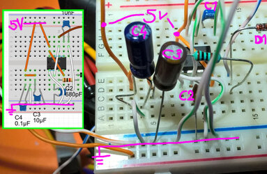
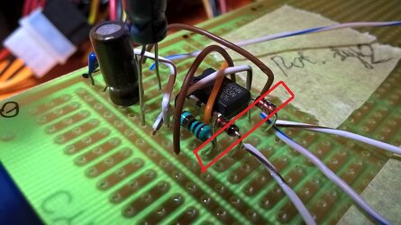
Sorry for bombarding the thread again but I've noticed something really curious about the circuit. Or my circuit. I'm pretty sure that by this point my breadboard wiring is correct. Yesterday I've decided to transfer the circuit to a perfboard. Test: it worked exactly the same as my breadboard circuit, so 'good to go', right? Not exactly. I took a second look at the perfboard circuit and it's clear that I forgot to power the path where positive leads of C3 and C4 capacitors are soldered onto. So my circuit works the same way with or without the C3 and C4 capacitors in the circuit.
Two photos of the perfboard circuit:
http://1drv.ms/1PvVnI1
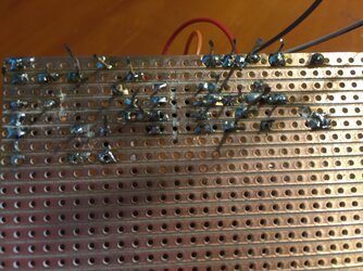
Connections established on the bottom surface of the board:
Pins 4 and 8 to 5V supply
pins of the two diodes as per schematic

I have used separate sets of capacitors for the two circuits so it's unlikely the capacitors are damaged.

555_problem.jpg

EDIT:
I took a jumper and connected/disconnected the branch with C3 and C4 capacitors with the circuit running connected to a fan. With the AMD stock fan (which whines with the 555 circuit) it only very slightly changed the frequency of the whining noise, and not in all RPM ranges. Only some. With my other fans there was no difference.

A reminder:
I use electrolytic capacitors.
 
Last edited:
Sorry for bombarding the thread again but I've noticed something really curious about the circuit. Or my circuit. I'm pretty sure that by this point my breadboard wiring is correct. Yesterday I've decided to transfer the circuit to a perfboard. Test: it worked exactly the same as my breadboard circuit, so 'good to go', right? Not exactly. I took a second look at the perfboard circuit and it's clear that I forgot to power the path where positive leads of C3 and C4 capacitors are soldered onto. So my circuit works the same way with or without the C3 and C4 capacitors in the circuit.
Two photos of the perfboard circuit:
http://1drv.ms/1PvVnI1
Connections established on the bottom surface of the board:
Pins 4 and 8 to 5V supply
pins of the two diodes as per schematic

I have used separate sets of capacitors for the two circuits so it's unlikely the capacitors are damaged.

View attachment 170940

EDIT:
I took a jumper and connected/disconnected the branch with C3 and C4 capacitors with the circuit running connected to a fan. With the AMD stock fan (which whines with the 555 circuit) it only very slightly changed the frequency of the whining noise, and not in all RPM ranges. Only some. With my other fans there was no difference.

A reminder:
I use electrolytic capacitors.

C3 & C4 is for noise filtering for the 5V power. Without those caps, any noise would change the frequency of the PWM signal some.
 
Two photos of the perfboard circuit:
http://1drv.ms/1PvVnI1
Connections established on the bottom surface of the board:
Pins 4 and 8 to 5V supply
pins of the two diodes as per schematic


WP_20151107_22_53_14_Pro.jpg

are you connecting both diodes via the white brown stripped wire?
try add a 2nd 555 as a buffer, and switch to 470pF + 100k pot for the frequency network

I'd also like to recheck the wiring if I were you,
especially on the diodes + 1k resistor section
 
Last edited:
View attachment 170964

are you connecting both diodes via the white brown stripped wire?
try add a 2nd 555 as a buffer, and switch to 470pF + 100k pot for the frequency network

I'd also like to recheck the wiring if I were you,
especially on the diodes + 1k resistor section
Such modification is out of my league unless there is a wiring diagram readily available.

The diodes are connected: anode of D1 to cathode of D2. The 3 wires to the right are pot 1, PWM and pot 3 , from the nearest. Pot 2 wire is further on the photo.
I'm done with checking the wiring. I spent a lot of time doing it and if something still wrong, I simply don't see it. This is why I have posted links to my wiring diagram (the one I use) as well as photos of my perfboard and breadboard. Again, only two connections are done on the bottom surface of my perfboard: anode of D1 to cathode of D2 as well as [Pins 4 and 8 of the 555 to 5V supply].


actually, that's the standard schematic for the 2-98% version on the other thread.
forgot on what page it is, but you should be able to find it around the first 20 - 25 pages.
more infos from the previous builder over there, so it's really worth the time to read (if you really like to build one)

sometimes, it's easier to rebuild the controller from scratch rather than trouble shoot one that failed.
and I'm pretty sure the 555 power pins are #1 & #8
 
Calling a circuit diagram 'standard' may become problematic :)
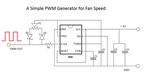
As far as this thread is concerned 'standard' best fits the first diagram from the article linked in the original post i.e. http://www.overclockers.com/wp-content/uploads/2010/12/PWM-circuit.png
I have transferred it to Fritzing getting this
http://www.overclockers.com/forums/...for-PWM-Fans?p=7845273&viewfull=1#post7845273
Now, if the two differ functionally by even a bit, we have the culprit so please let me know if you see any differences. In the few recent posts I reversed the diod numbering, D1 being the one closer to the 555.

Regarding power pins of the 555. On both of the diagrams (which,again, should be equivalent) 5 goes to pins 4 (Reset) and 8 (VCC).
 
Last edited:
Quick question...

Hi, I've ordered all the required parts to create the multi-fan PWM signal generator using the 556 IC. I'm actually modifying an entertainment center to have variable speed cooling fans for a console replacement/HTPC ITX build. I'd like the fan array to run off of a 12V power power adapter plugged into the wall instead of a molex from the PC. My question is, can I use an L7805 5V regulator to step the voltage down for the PWM circuit running in parallel with the 12V fans. Would there be any issue tying everything back into the common/ground on the 12V wall adapter?

Thanks for your help!

Edit: My latest post in the original thread contains more specific questions and a circuit diagram made with MS Paint!
http://www.overclockers.com/forums/...ng-PWM-Controller-for-4-wires-PWM-fan/page108
 
Last edited:
The 555 uses very little current so if that's all you're running, a 7805 will work just fine.
 
Hi!

I've assembled the controller on a strip board, but it seems that the pwm signal doesn't change :/
I'm using an AC Freezer64 Pro from a 12V source, and a step-down to supply the 5V to the circuit, if I plug the fan in it spins at max, when I plug in the pwm pin it slows down to minimum (I think), but there's no change when I adjust the potentiometer :/
Any advice on how can I debug the circuit is welcome, I'm a total newbie in terms of circuits and soldering :(

Here are some photos of the board and the setup, I've cut the lines with a yato knife.

I'm a noob too but I did my share of troubleshooting this project. I'd gladly help but what you have posted is really hard to follow. Could re-create exactly the same physical connections using breadboard or Fritzing? Did the circuit work using breadboard?
 
I'm a noob too but I did my share of troubleshooting this project. I'd gladly help but what you have posted is really hard to follow. Could re-create exactly the same physical connections using breadboard or Fritzing? Did the circuit work using breadboard?

Hi!

I don't have a big breadboard, so I tried my luck with the stripboard :D
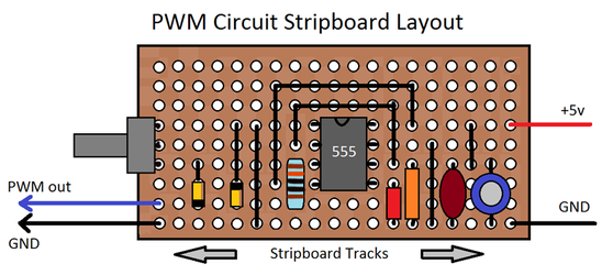
I've followed the layout on this picture:
pwm-stripboard-with-components.png

Then cut the stripes on the back to make the connection as on this circuit diagram:
PWM-circuit.png

I'll go to the nearest city and pick up a big breadboard, then try it again, I have enough components to make two of this simple 555 pwm generator.
 
Hi!

I don't have a big breadboard, so I tried my luck with the stripboard :D
I've followed the layout on this picture:

Then cut the stripes on the back to make the connection as on this circuit diagram:

I'll go to the nearest city and pick up a big breadboard, then try it again, I have enough components to make two of this simple 555 pwm generator.

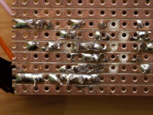
I hope your soldering is better than this:
trackbreaks-300x225.jpg
:rofl::chair:
 
Okay, assembled the thing on a breadboard, if I remove the C2 capacitor it adjusts the fan but just a little :S
 
if you happen to have two of the 555 (the 556 consists of two 555),
I suggest you try the circuit here:
http://www.overclockers.com/forums/...ires-PWM-fan?p=6473318&viewfull=1#post6473318

Unfortunately I don't have the extra components this circuit needs, and the shop is closed by now :/

I'm pretty sure that the breadboard circuit is good, but it just doesn't work. The fan connected to +12 and gnd, and the blue wire (pwm) goes to the pwm out.
I could only make it change if I remove the 680pF capacitor and just connect that part to GND, :/ (I can switch the fan between two states with the potmeter)

- - - Updated - - -

OMG, I forgot to connect the PIN1 of the 555 to the GND -.-
The breadboard circuit is working, time to find the issue with the stripboard version :D

Thank you for everyone for the help!!!

:rofl: There are 3 rules to breadboarding, 1. Check connections, 2. Check connections, 3. Check connections :rofl::chair:

- - - Updated - - -

I'm not sure :D

Trim the wires and component leads so they don't get bent down and short on something else.


p.s. Go back 2 pages and look at my board :rofl:
 
Last edited:
Back