- Joined
- Dec 25, 2004
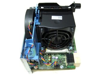
I need to find a fan that will plug into this fan header (the lower 4pin one, not the 5pin higher one):

This is a fair amount smaller than the normal CPU 4pin connector. But it is larger than the 4pin connector like you find on some video cards.
Any idea what I need to look for, or where I can find a fan that will fit?
Thank you.

This is a fair amount smaller than the normal CPU 4pin connector. But it is larger than the 4pin connector like you find on some video cards.
Any idea what I need to look for, or where I can find a fan that will fit?
Thank you.