• Welcome to Overclockers Forums! Join us to reply in threads, receive reduced ads, and to customize your site experience!

FEATURED Building PWM Controller for 4 wires PWM fan

Overclockers is supported by our readers. When you click a link to make a purchase, we may earn a commission. Learn More.
Hi everyone
I've been looking through this thread for quite a while now and have been using the search function (apparently I suck at searching)

Can someone point me in the right direction please

I want to run 8 max fans off one channel and use the motherboards software to control the speed, do any of the schematics allow this,
if so, which one/s

Thanks
 
Thanks for replying, not available on amazon.co.uk though

I've pretty much got all the parts laying around for the schematic on page two, but as far as I'm aware
that's pot controlled, is there a way to make that one motherboard/software controlled ?
 
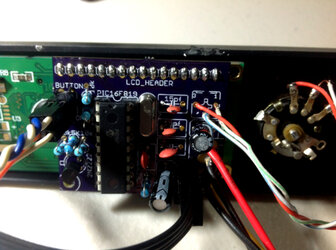
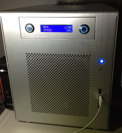
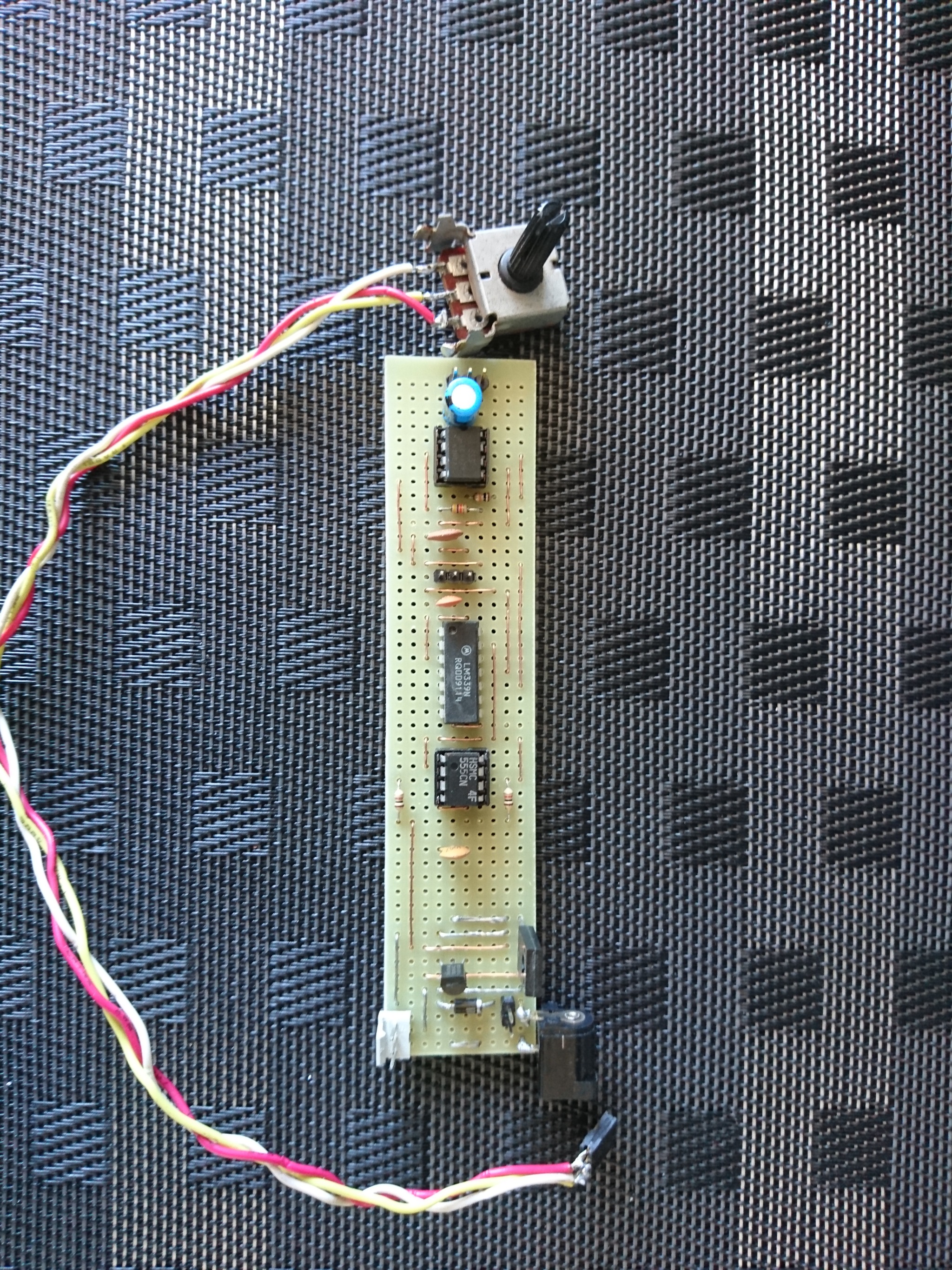
I've got source code, eagle files, and gerber files available for anyone who wants to make their own pwm controller based on a pic microchip for complete fan control with changeable frequency. I made the controller years ago then abandoned the project from further development. No sense in keeping it to myself. I used oshpark for the pcb, very reasonable.

Here is a pdf describing the project.

View attachment PWM.pdf

IMG_0107.JPG

IMG_0309.JPG

I made it for San Ace 12V 4 amp fans. I have two fans left over from the project in the classifieds section. Unfortunately, I have no finished controllers other than the one I am using.

The programming is for mickoc. Pretty easy to adapt this schematic and programming for other fans / voltages, etc.

Here is a zip with the Eagle files, the mikroC project, and some useful files like a pinout for the 16x2 display, a flow chart for the programming, and a sketchup file for the controller. The sketchup file has an older version of the pcb in it, but it is basically the same concept.

View attachment pwm_lcd_project.zip

The following section of code should be updated, it didn't compile as it was written in the new version of mikroC:

Code:
void updateLCD() {                              // begin function for updating the lcd
      unsigned char convertit;                  //
      char buf[16];                             // character buffer for the lcd
      convertit = pwm_duty / 255 * 100;         //
      WordToStr(convertit, buf);                // convert the duty cycle to string data and put it in buf
      strcat(buf, "%");                         // append "%" to the character buffer
      Lcd_Out(2, 13, buf);                      // print out the data on line 2
                                                //
}
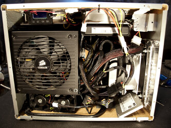
I had to piggyback the tach signal back to the header on my motherboard to get the computer to post. That's one detail to keep in mind if you can't get the PC to boot.

...

It ends up Oshpark lets you share files, so here is a permalink to my last order for building the controller.

https://oshpark.com/shared_projects/NPQUebch
 
Last edited:
I found a good cheap alternative on ebay for anyone who needs a controller and doesn't want to build their own. I'm using one right now to control the two new san ace fans in my system.

https://www.ebay.com/sch/i.html?_from=R40&_trksid=m570.l1313&_nkw=XY-LPWM&_sacat=0

I found files to 3D print a case for the controller, and it turned out nicely.

https://www.thingiverse.com/thing:2863707
There is a remix of the cover that allows for the communication pins:
https://www.thingiverse.com/thing:2863707/remixes

You can see it in the top left corner of my case:

P1013163.jpg
 
im not sure if its been asked before but could the schematic with the dual 555's (correct me if im wrong) by bing work with say a circuit on the same board that coud take 24v down to 5v before going into the pwm controller?

sorry if i worded it in a stupid way haha
 
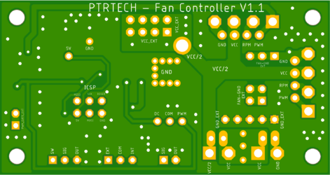
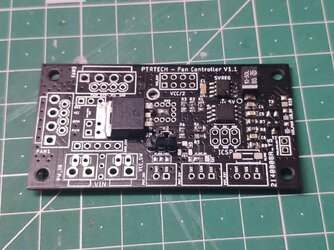
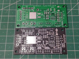
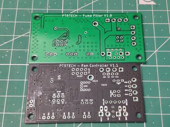
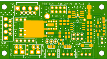
Some time ago i needed some kind of PWM fan controller for a project i'm developing, i found this post and start experimenting with 555. It works, i feed two beast fans in parallel for sometime. But recently i found that the circuit is not following the intel specs: http://www.formfactors.org/developer...e_PWM_Spec.pdf
Fans require a Open collector/Drain signal without any pullup resistor, that's what wrong with the published circuit. After analyse with a oscilloscope when fan is connected, signal get's so noisy that is unreadable, for my surprise fans work like that. After read specs parallel connections and incorrect drive can lead to wrong speed and damage fans if their circuit is sensitive. That way i come with my solution:

PWM Signal: 5V, 25KHz, Open collector/Drain
Input Voltage: 7V to 50V, must use same voltage the target fan.
PWM Mode can use T1 up to 6A without heatsink (I only test that far with real fans (24V 3A x 2))

Features:
- Set fan speed by a potentiometer or fixed by software
- Two potentiometer inputs with a selector switch (INT or EXT)
- Instant disable/enable fan by a click button (Doesn't lose last speed setting)
- Fan kickstart on boot or reenable (Software configuration)
- Can control two and three wire fans as other loads as well by DC switching (JP_FAN_MODE Jumper), v1.1 only! Require heatshink on T1 FET!
- Up to two fans or 10 with expansion board (v1.1 only), expansion board not made yet.
- Diferent fans per header are compatible but input voltage must be the same for all
- v1.1 have multiple component design that allow to choose between one regulator or another, based on max. input voltages to save some bucks
- Fan headers: VH3.96 up to 10A fans OR XH2.54 for up 3A fans (v1.1 only)

alWywY0.png
gnnA34b.png
GHDwpl9.jpg
piJY1If.jpg
CzUtzcf.jpg
 
I've been meaning to post in this thread for a while now but haven't got round to it - I even had to reactivate my account because it's been four years since my last post (thanks mods!). I know it's a little late, but it's worth replying to sn4k3 above to reiterate that the original 555 circuit was superseded by the 0-100% controller, which I have been using for several years now and have employed to successfully test many high powered fans. Whils the 555 or 556 circuits are an easier option for the beginner, I'd strongly recommend building the 0-100% version.

I think it's worth keeping this thread "alive" because it's always nice to see where enthusiasts take these designs, and it's also interesting to keep up to date with PWM fans that are new to the market. Since this thread was started, there have been two notable fan releases: the 2150rpm model of the Gentle Typhoon (Nidec Servo D1225C12B6ZPA) which is a 4-wire PWM fan; and the Noctua NH-A12x25, a direct competitor to the Nidec, also a PWM fan. In time I'd like to do my own testing with these fans, especially to compare them to 120x38mm "server" fans. The Noctua especially is very expensive for a standard 120mm case or heatsink fan, and for me it's very cleverly marketed but woefully overpriced.

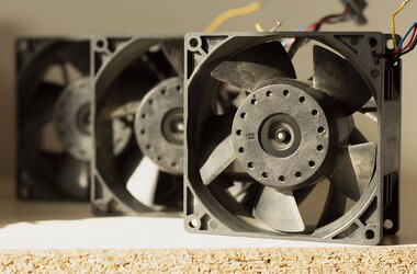
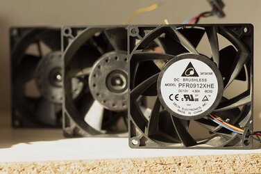
Anyway, onwards to some pictures. I recently came across three very powerful 92x38mm Delta fans, model PFR0912XHE, which I purchased for equivalent to a little over $3 each (yes, you read that correctly). These are 11,000rpm fans which draw a little under 4A at full speed, though 4.5A is printed on the label. Unlike most of the Deltas I have, the frame and impeller are both made from fibre-reinforced plastic, which is what San Aces tend to be made from.

With the 0-100% controller the behaviour is very interesting, but as you'd expect the control is pleasing because of its accuracy. The PWM signal is not inverted and at low RPM the fan is inaudible.

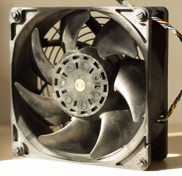
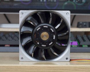
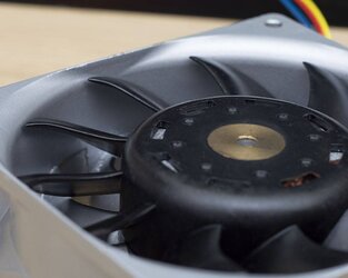
I also got a 140x50mm San Ace which is a beast. It's only 1.8A but because of its size has the capacity to move 220cfm at 3,000rpm. Some pics for now and I'm planning to make some videos in the near future.

tJn3QO.jpg

06vnmZ.jpg

9xxwql.jpg

ivvWog.jpg
 
Hi everyone,
I set up the circuit, the frequency was around 23kHz, but in a given duty cycle range the cooler produces a very annoying noise, I changed the frequency to more and less without very successful (in some cases it reduces a little but does not stop). I used a new pc processor cooler, I know that on the pc it doesn't make that annoying noise, so is there anything I can do to improve it?
Thankful.
d7cdb1a9f290f5eebe5320e07ceba8327583a520.jpg


- - - Auto-Merged Double Post - - -

Sorry for the audio not being good in the video ...
 
Hi everyone,
I set up the circuit, the frequency was around 23kHz, but in a given duty cycle range the cooler produces a very annoying noise, I changed the frequency to more and less without very successful (in some cases it reduces a little but does not stop). I used a new pc processor cooler (3 wires), I know that on the pc it doesn't make that annoying noise, so is there anything I can do to improve it?
Thankful.
d7cdb1a9f290f5eebe5320e07ceba8327583a520.jpg


\Sorry for the audio not being good in the video.
- - - Auto-Merged Double Post - - -

Hi everyone,
I set up the circuit, the frequency was around 23kHz, but in a given duty cycle range the cooler produces a very annoying noise, I changed the frequency to more and less without very successful (in some cases it reduces a little but does not stop). I used a new pc processor cooler (3 wires), I know that on the pc it doesn't make that annoying noise, so is there anything I can do to improve it?
Thankful.
d7cdb1a9f290f5eebe5320e07ceba8327583a520.jpg


Sorry for the audio not being good in the video.
 
Hey Fabio! Nice work on the controller - it looks like you've made some modifications to the circuit so it's quite different from the 5v PWM signal generator.

I built a similar controller a while ago and it fed a square wave pulse on the 12v supply line to the fan. Whilst you can successfully control a fan's speed this way, it's not as efficient and I found that in the low duty cycle range of maybe 0-15% the fan made annoying noises. To the best of my (limited) knowledge of electronics, I don't think you can fix this. Have you tried making the 0-100% circuit for 4-wire fans? It's ideal if you want to have no strange noises!
 
Hi LennyRhys, thanks
The modifications I made were minor, I did not use resistors together with the potentiometer to limit the control range (so part of the axis travel at the beginning and end of the potentiometer has no effect) and the pwm output I connected to a mosfet because in my project I will use a 3-wire cooler. I have already read some materials that indicate to use capacitors to smooth the beginning of the square wave of the pwm, I will test this because it is very irritating the cooler in some ranges of rpm to make noise which does not happen when this cooler is connected to a motherboard ( PC) and is controlled by it, so there must be something to alleviate that.
Thank you.
 
So I've joined the Nidec "super fan" club with the G1238B12BBZP-F00, which has the highest static pressure of any 120mm 12v fan. This fan really is a masterpiece of engineering and design... the tolerances, the aerofoil-like impeller blades, and the staggering performance are just something to behold!

g88A4X.jpg
kQu45d.jpg

I'm planning to do a short series of videos about the controller in this thread and why it's a great idea to repurpose used server fans in PC builds. Here's a teaser that I put together to test some footage and see what sort of time commitment the project might require.

 
Hello, as I have several fans of this type (3 wires), and after several tests I ended up opting for linear control but I used a PWM control (DC / DC converter with an MC34063A). I did a test using an arduino with 490Hz pwm adapted in the feedback of the MC34063 and it can vary from 1Volt to 12V the output voltage. With 1 Volt the fan has no current consumption, that is, it is completely switched off by undervoltage, which is very good.
Finally, the control works without annoying noises starting with something around 3.7V and with perfect control in the tests, now I want to think of something to measure the RPM.
View attachment 209899
 
I've been meaning to post in this thread for a while now but haven't got round to it - I even had to reactivate my account because it's been four years since my last post (thanks mods!). I know it's a little late, but it's worth replying to sn4k3 above to reiterate that the original 555 circuit was superseded by the 0-100% controller, which I have been using for several years now and have employed to successfully test many high powered fans. Whils the 555 or 556 circuits are an easier option for the beginner, I'd strongly recommend building the 0-100% version.

I think it's worth keeping this thread "alive" because it's always nice to see where enthusiasts take these designs, and it's also interesting to keep up to date with PWM fans that are new to the market. Since this thread was started, there have been two notable fan releases: the 2150rpm model of the Gentle Typhoon (Nidec Servo D1225C12B6ZPA) which is a 4-wire PWM fan; and the Noctua NH-A12x25, a direct competitor to the Nidec, also a PWM fan. In time I'd like to do my own testing with these fans, especially to compare them to 120x38mm "server" fans. The Noctua especially is very expensive for a standard 120mm case or heatsink fan, and for me it's very cleverly marketed but woefully overpriced.

Anyway, onwards to some pictures. I recently came across three very powerful 92x38mm Delta fans, model PFR0912XHE, which I purchased for equivalent to a little over $3 each (yes, you read that correctly). These are 11,000rpm fans which draw a little under 4A at full speed, though 4.5A is printed on the label. Unlike most of the Deltas I have, the frame and impeller are both made from fibre-reinforced plastic, which is what San Aces tend to be made from.

With the 0-100% controller the behaviour is very interesting, but as you'd expect the control is pleasing because of its accuracy. The PWM signal is not inverted and at low RPM the fan is inaudible.

I also got a 140x50mm San Ace which is a beast. It's only 1.8A but because of its size has the capacity to move 220cfm at 3,000rpm. Some pics for now and I'm planning to make some videos in the near future.

Nice photos & videos , thanks. :attn::salute::clap:

Amazing, this thread is still alive after all these years. :shock:
 
@bing Nice to see you are still alive too - it is thanks to you that we got as far as we did! I hope you are well dude.

I think for me it's gonna be a case of fans till I die... I just love the physics of fans and tinkering with them is great fun.

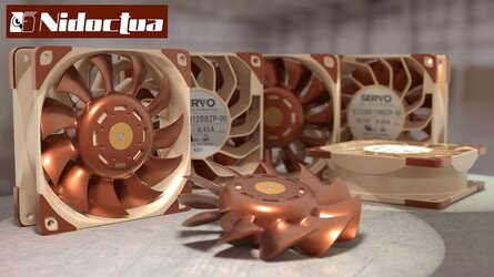
Also, I made a 3D render this weekend to mash up two fans - the Noctua A12x25 and the Nidec G1238B. I hope you like it. :D

m1kQ2J.jpg
 
Back