• Welcome to Overclockers Forums! Join us to reply in threads, receive reduced ads, and to customize your site experience!

FEATURED Building PWM Controller for 4 wires PWM fan

Overclockers is supported by our readers. When you click a link to make a purchase, we may earn a commission. Learn More.
PWM Controller

I had no interest in developing the pwm controller I wrote into a commercial product, but a guy from the forum who lives in Australia wanted to use it to control a custom stir plate for his microbrewery.

We've done quite a bit of work on the original product, and now are nearing production stage. I think he'll be offering them on ebay as kits that you can put together yourself, manufactured and masked pcb, dip sockets, pre-programmed chips, and all other needed components.

Here's a preliminary list of functions.

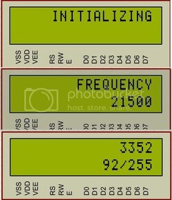
1) startup displays your currently selected frequency
2) an initialization period between 0-5 seconds that ramps the fan up to your stored pwm duty cycle. Makes for a quieter start up, less jerking on the fans.
3) afterward there is a constant display of pwm duty cycle and current fan rpm data.
4) duty cycle is controlled by up and down buttons. This is saved between shut downs to the physical memory of the chip.
5) pressing both buttons together changes the pwm frequency between 16k, 21.5k, and 24k. This is saved between shut downs to the physical memory of the chip.
6) periodically checks for changes and saves them, to avoid making constant changes to your saved settings. (I.E. doesn't burn out the EEPROM chip.)
7) powered by the 12v of a molex connector, powers the fan that is plugged into it.

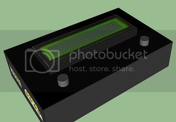
Here's some mockups.

PWMCONTROLLERV2_zps781780fa.jpg

PWMCONTROLLERV2_top_side_zpse62e58ea.jpg

PWMCONTROLLERV2_side_zps4a85b4d8.jpg

freq_zps62d733e8.jpg

I'll try to post more information as I get it, if any of you guys may need one.
 
Very nice!
The controls are similar to my pushbutton two-channel controller, though mine lacks a display screen (having that is a nice feature!).
Please keep us updated, I want to see it as it happens!
 
Very nice!
The controls are similar to my pushbutton two-channel controller, though mine lacks a display screen (having that is a nice feature!).
Please keep us updated, I want to see it as it happens!

Oh, it's happening. I filed a defensive publication to prevent anyone in the world from obtaining a patent on the technology and I reserved the right to patent it in the United States for up to a year from now.

I'm kind of excited. It works really nice and smooth in the simulator. I can't wait till the guy gets his parts in and I can send him the hex file to test the program. The pcb layout is done too, and it couldn't have been simpler. 4 resistors, 4 capacitors, a 18 pin dip socket for the chip, 2x2 pin header, and a 16x1 pin header. Super simple pcb layout, all on one side except for two jumper wires on top. It was unavoidable.
 
Yeah, really nice renders. I suck at making things pretty like that.
Good luck with your proyect.

Thank you. I designed and developed an entire google sketchup in painstaking detail for a house my mother, brother, and I are planning on building in a year. That gave me enough exposure to make stuff in sketchup super easy. You should try it! Google sketchup is free and ROCKS!
 
Good luck on the patents, I have posts for a multi-frequency PWM fan controller here on OCF from last year, prior art on that one.
 
Good luck on the patents, I have posts for a multi-frequency PWM fan controller here on OCF from last year, prior art on that one.

I was more concerned with someone else filing one and telling me I had to stop production lol. I would hate for someone to take my code and tell me I had to stop programming microchips with it because it was now "their's". Isn't it crazy that people have done that?

Also, you can obtain a patent if it improves an existing technology or innovates in a way that the other does not. This is why I can still develop and patent custom gauges for cars, even though there are already custom gauges out there. I just need to do it in a way no one else has, using different technology. That's why I chose pic microcontrollers, they are less common in the mcu industry.
 
That's what publishing and prior art is for, but yeah it's a screwed up system.

Yeah, it's totally retarded and SO EXPENSIVE. I think prior art is the way to go.

The sickening thing is it doesn't protect you, and neither does a patent, from making an extremely similar product with only minor differences. That's why there are so many manufacturers of computer mice, keyboards, etc... The smallest change and it qualifies for it's own patent. You could have two identical keyboards, and if they use a different circuit board to control it it's a new invention.

:screwy:

Personally, I was more concerned with someone opening up the controllers we build, copying my code, then filing a patent and telling me I had to develop an entirely new one. That was hundreds of lines of code! Setting up the timing libraries alone to give me proper interrupts for my saving and refresh routines about had me pulling me hair out last week.
 
"Best" is hard to define, but that setup should work just fine and do what you want it to.
 
I'm hoping someone still looks at this ancient thread. Just to start off, I have no idea how to read a schematic or what most of these parts even do. I set up a bread board to the T following this picture (http://www.overclockers.com/wp-content/uploads/2010/12/pwmcontrollerMM.jpg) However, when I hook the PWM wire to a fan nothing happens. It continues to spin at 100% no matter what the potentiometer is turned to. I'm not sure if I have a wiring problem (checked it over 10 times wire by wire), I got wrong parts (listed below), or what my problem is. I think my main problem is I don't know how to trouble shoot what is wrong or how to test of it's even doing anything. Pretty much all I have for testing is a digital multimeter. There is (what I assume is a constant) 4.81v coming off the PWM wire. If the parts will work I can upload a picture of the breadboard but its pretty messy since I have long wires.

These are the parts I'm using (all from radioshack):
http://www.radioshack.com/product/index.jsp?productId=2062597 556 timer
http://www.radioshack.com/product/index.jsp?productId=2103628 .01µF capacitor
http://www.radioshack.com/product/index.jsp?productId=12579976 560pf capacitor This should be a 680pf capacitor but this is all I could find. I read almost all 68 pages of this thread and saw a post mentioning that this should work, but the frequency may be off and the fan may make noise. I had to buy an assorted pack of 100 capacitors just to get 1 of these 560pf's. I have plenty of dead electronics laying around if anyone knows of common items that have these I can steal from.
http://www.radioshack.com/product/index.jsp?productId=2102509 10µF capacitor
http://www.radioshack.com/product/index.jsp?productId=2103630 0.1µF capacitor
http://www.radioshack.com/product/index.jsp?productId=2062296 1k resistor
http://www.radioshack.com/product/index.jsp?productId=2062287 Potentiometer
http://www.radioshack.com/product/index.jsp?productId=2062576 Diodes
http://www.radioshack.com/product/index.jsp?productId=2062330 10k resistor
I'm using a stock Intel heat-sink/fan combo for testing but I have about 10 other fans with PWM wires that I tried and they do not work either.

I know I went overboard on some of the parts but they were out of some of the smaller capacitors and resistors.
 
Can you post a picture of your breadboarded controller? Odds are it's something simple, a single wire one space off will prevent it from working. It sounds like it's stuck at 98%, (unless your psu's idea of 5v is low), so it's something involving the pot.
 
Here it is. I checked it probably 50 times by now. The only thing I'm unsure about is the part circled in red. I have the positive side of the 10µF capacitor in the same row as the red wire (5v) and the negative side in the row directly to the left. The 0.1µF capacitor is in the same rows just down a column and the ground is coming off the row the 10µF capacitor negative side is on. Where do I even start to trouble shoot what isn't working?
 
Last edited:
It all looks good to me, too. I assume that the red leads on the right go to the pot (with the middle red wire going to the middle of the pot). There are a couple things (namely the 100ohm resistor) that I can't quite see where they plug in though.

Below I've circled a spot on the breadboard, please make sure that the power/ground rails are connected on both sides of that spot. Note that the gap between 5hole runs is slightly larger, some breadboards have an electrical break in this spot that has to be jumped. If that's the case for this one there is no ground for the 556 and it won't work.


View attachment 130950
 
You nailed it...there's a break there. I moved that blue wire between the 2 capacitors and it works like a charm now, thanks so much!
 
Back