• Welcome to Overclockers Forums! Join us to reply in threads, receive reduced ads, and to customize your site experience!

Journey to geothermal

Overclockers is supported by our readers. When you click a link to make a purchase, we may earn a commission. Learn More.
I agree!

I'm just curious as to what he made regarding the copper cooling manifold that's at the bottom of the hole?

I know, a picture or 2 would have been helpful. But I can explain it.
I used 4 10' lengths of 1/2" hard drawn copper pipe, 6 90 degree solder joint fittings, and 2 press in fittings.
I silver soldered the 90s together using 1 inch inserts into 3 U-shaped fittings. Then I soldered the Us onto the ends of the straight pipes. What I ended up with is a copper pipe going 10 feet down into a U, then 10 feet back up into the next U, Then 10 feet down into the third U, and then 10 feet back up. So I have 40 feet of copper pipe in a 10 foot by 2.5" package. On the open ends of the pipe I installed the copper press-on fittings to attach the PEX tubes. I vacuum filled the whole thing to eliminate any air pockets.

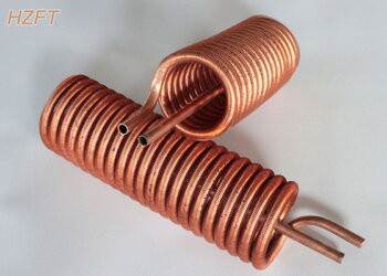
If I were to do it again I think I would use 3 50 foot 1/4" soft drawn tubes run in parallel. I would coil them around a length of 2" PVC and then pull the PVC out leaving the coils. This configuration would put more of the water in the system in direct contact with the tubing walls for better heat transference. I thought of doing this originally but went the easier route with respect to building and soldering the manifolds.
 
Anyone else impressed with the pump going through well over 110' worth of piping?


Not sure you would want to go down to 1/4" though... that, IIRC, and silver can tell us more, but i vaguely recall some testing stating to be above 1/4" for best flow rates/results. With that much travel and restriction, the pump may not work well there.
 
Last edited:
Anyone else impressed with the pump going through well over 110' worth of piping?


Not sure you would want to go down to 1/4" though... that, IIRC, and silver can tell us more, but i vaguely recall some testing stating to be above 1/4" for best flow rates/results. With that much travel and restriction, the pump may not work well there.

From 1/4" to 1/2" you wind up loosing about 1C or so of cooling potential.

I have the link on my desktop to a thread here on the subject lemme dig it up

Okay here we go: http://www.overclockers.com/forums/showthread.php/515368-The-impact-of-tubing-sizes

Global temp = 22C
Room C/W = 0.005
Fan Heat Dump = 2.0W

The proposed tubing sizes and fittings we'll be investigating are:

6.35 (1/4") ID tubing with quick-fit fittings
8mm (5/16") ID tubing over 6mmID|8mmOD barbs
8mm (5/16") ID tubing with quick-fit fittings
9.6mm (3/8") ID tubing over 7.5mmID|3/8"OD barbs
9.6mm (3/8") ID tubing with quick-fit fittings
11.1mm (7/16") ID tubing stretched over 10.5mmID|1/2"OD barbs
12.7mm (1/2") ID tubing over 10.5mmID|1/2"OD barbs

The total CPU heat load is 100W. The total system heat load is 114W . We assume a fixed 14W heat dump from pump which was derived from other testing. This does in fact vary a little as we can see by the Laing graph. As flow rates decrease, so does power draw, and therefore the heat-dump as well. For simplicity we'll assume a fixed 14W heat dump for now.

The intersections all are:

6.35mm quick fit = 4.45LPM flow, 0.0795 block c/w, 0.0374 rad c/w
8mm barbed = 4.75LPM, 0.0783 block c/w, 0.0373 rad c/w
8mm quick fit = 5.6LPM, 0.0770 block c/w, 0.0369 rad c/w
9.6mm barbed = 5.7LPM, 0.0768 block c/w, 0.0369 rad c/w
9.6mm quick fit = 6.2LPM, 0.0762 block c/w, 0.0367 rad c/w
11.1mm barbed = 6.3LPM, 0.0761 block c/w, 0.0367 rad c/w
12.7mm barbed = 6.35LPM, 0.0760 block c/w, 0.0366 rad c/w

Final CPU temperature is ambient (22C) + system load (114W) * radiator C/W + CPU Load (100W) * block C/W

The final CPU temperatures work out to be:

6.35mm quick fit = 34.21C
8mm barbed = 34.08C
8mm quick fit = 33.91C
9.6mm barbed = 33.89C
9.6mm quick fit = 33.80C
11.1mm barbed = 33.79C
12.7mm barbed = 33.77C
So yeah, 1/4" will reduce the flow rate, but I wonder if the increased speeds in which the water flows in the 1/4" pipe would help the water travel up and down the pipes?
 
Last edited:
Thanks other silver!! Indeed it isn't much. I am more concerned with the pump being able to handle that than anything as it would put more stress on the pump, the smaller it goes I would imagine.
 
I said three 1/4" tubes but I meant four 1/4" tubes.
I would put the four 1/4 tubes in parallel with one another. It would look like the picture that Surfer posted but it would be 4 separate coils. Then I would make two 4 into 1 (1/4" to 1/2") manifolds. The manifold is where the PEX would joint the copper. I originally tried to do a coil with 1/2" soft draw copper tube but It wouldn't bend to such a tight radius to fit in the 3" hole.

Why 4 1/4" tubes you may ask.
Area of the 1/4" tube is .04909 x4 tubes = .19636"
Area of the 1/2" tube is .19635"
This would eliminate any flow restrictions.

I was running out of time to make the manifolds so I went with the simpler option.
 
Last edited:
Back