• Welcome to Overclockers Forums! Join us to reply in threads, receive reduced ads, and to customize your site experience!

LED Voltage on Illuminated Anti-Vandal Switch

Overclockers is supported by our readers. When you click a link to make a purchase, we may earn a commission. Learn More.

skorpien

Member
Joined
May 9, 2011
Location
Alberta, Canada
Hi all,

I have a whole bunch of illuminated anti-vandal switches that I'm using in my build, both momentary and latching. As I have a multitude of devices that I'll be controlling with these, I thought I would do my own wiring. I am a little confused about the LED voltage requirements of these switches.

I purchased them from PPCs, and although most of them had the same packaging, I had two momentary switches that were branded Lamptron that came with some confusing instructions. There were two sets of instructions with these, one stapled to the outside and one sealed inside the package itself. The one on the outside said that the LED voltage was 3.3 (or similar) max, while the instructions sealed inside the package said they were 3.4V, 5V, or 12V. (The other switches all said the LEDs were rated for up to 12V so I'm not concerned.)

I'm thinking of playing it safe and using the 3.3V for all of them, though I'm concerned that the glow of the LEDs won't be as bright with the lower voltage. I'm also worried about burning out the LEDs in the Lamptron switches if it actually isn't rated for 12V.

Secondly, there's another thing causing a bit of confusion on my part. The instructions that come with the switches are all identical with two drawings and the only thing that distinguishes the two drawings are the words "common" and "push down"... I was under the assumption that common means momentary and push down means latching, but the instructions with the Lamptron switches also differ in this regard. The switches themselves are momentary but the drawing in the instructions stapled to them was the same as the "push down" diagram on the instructions inside.

Any insight would be greatly appreciated.
 
I'm not sure myself, no experience in this area - but you may try also posting in the modding section. Not certain, but I would guess there may be similar experience hanging out over there.

Also, maybe try shooting spawne32 a PM: http://www.overclockers.com/forums/member.php?u=51389

He hasn't been around much the past couple weeks, but he's a lamptron guy and could probably advise. :) If you get help in PM, just post it back here so others can learn too. :D
 
The LEDs themselves don't really care about voltage, as long as it is over their required minimum (generally ~1.8v for red, 3v for others). What LEDs care about the the amount of current flow. Lightbulbs are self-limiting (to an extent, anyway), LEDs on the other hand will draw as much current as is available and will burn up. To prevent this, a resistor needs to be placed in-line with the LED. This is a "Current limiting" resistor, which does exactly what the name implies. The trick is, the amount of current you get over a given resistor varies based on the voltage. That's where the rating on the switches comes in. The switches that say 3.3v have a built in resistor to keep the current at the correct level for a 3.3v source voltage. Similarly the 12v switches have a resistor to keep the current at the correct level at 12v. If there is any external wiring/connection for the illumination LEDs you can simply add a resistor to allow the 3.3v switches to work at 12v without burning out. Going the other direction is trickier, as you'd need to remove the current resistor and put a lower resistance unit in place.

What I would do is test them on 3.3v and see how bright they are, if they're quite dim try 5v. Still quite dim? Try 12v. If it dies on 12v you know it was a 5v unit Alternatively, use the current checking abilities of a digital multimeter to see how much is being drawn by the LED at 3.3v, if it's <10ma try 5v. If it's still less than 10ma, it may be a 12v unit. You can also use the LED color and the current and the source voltage to figure out roughly what resistor is already in place.
 
Last edited by a moderator:
Well, I'm definitely glad I purchased that digital multimeter now, it's proving more useful the longer I have it.

Thanks Bobnova, I'll give that a try over the weekend. Had no idea about the LEDs and currents :)

So let me see if I have this right... If a switch has LEDs rated for 12V and the LEDs are connected to a 3.3V source, the resistor in place would mean that the LED would be getting a lower current than it would if I used a 12V source, right?

Using R=V/I the LEDs would be drawing 10 mA over 12V, meaning it would be a 1200 Ohm resistor. And 1200 Ohms with 3.3V would make 2.75 mA (I hope I have that correct). That translates into a dimmer LED or would the LED not light at all?

Just trying to grasp the science behind it...

Edit: Somebody in my other thread explained the difference between common and push down. I think I had the terms confused, and common is actually the latching switch and push down is momentary. Here's a link:

http://www.overclockers.com/forums/showthread.php?t=720027
 
Last edited:
With 2.75ma you'd have a dim LED, but it'd still be lit. Possibly not enough to illuminate the switch housing.

Resistance wise you're very close, the trick is that you have guess at the "forward voltage" of the LED and take that off the input voltage. For example, with a blue LED we can guess a forward voltage of 3v. Connected to a 12v source the LED blocks/removes 3v, leaving 9v for the resistor to work with current wise.
That same LED on a 3.3v rail only leaves 0.3v over the resistor.
The extra trick is that red LEDs use a lot less, generally in the 1.8v to 2.0v range, it complicates things a bit :D
That said, you're on the right track.
 
So, basically, I should stick with testing the current with the digital multimeter :p

Nah, I think I got it. It all makes sense in my head, and I think I'll be able to tackle this now and actually understand how it all works (maybe not completely, but much better than when I started).

Thanks again :)
 
Electronics power our lives. Once and a while you see these things come up if your not a basic consumer. Then you see OMG this stuff is complicated!

I taught AF repair electronics for a radar system and taught basic repair electrionics also. We had a high washout rate. I could tell by their entry scores sometimes if they had the 'brain' to do it. I can't imagine what BN went through for years and how many calculator batteries he killed.

I bow down to the few EE guys we have here. To make it though the schooling and the brainiac to understand it still amazes me.

Thanks BN, few forums have folks like you.
 
You're welcome! I'm happy to help :D
I sidestepped most of the schooling and dove straight into the Arduino deep end. I've had the luxury of being able to focus on electronics without too much in the way of distraction for some time now, that's extremely helpful. Not having to do it for a job or for school means I can look into things that are interesting rather than memorizing things. It leads to rather spotty knowledge, but when you're interested in what you're learning the whole learning process works a lot better.
That LED/Resistor thing took me months to really nail down, if I even have now. It's even more awkward in that at voltages below the forward voltage drop of the LED it still leaks current and will shine, just very dimly. This is glossed over or skipped entirely by most online guides for some reason.
See what I mean about me being interested? I end up spewing it everywhere! :D

Anyway, it's nice to be appreciated, thank you!
 
See, this is what I like about OCF. There are very knowledgeable members more than willing to help, and people here seem genuine and appreciative. My sincerest thanks to you both :)
 
What I would do is test them on 3.3v and see how bright they are, if they're quite dim try 5v. Still quite dim? Try 12v. If it dies on 12v you know it was a 5v unit :D

This testing process has been reviewed by the administration and been approved. :salute:
 
I wish I had a bomb attacted to my PC so that if someone steals it they get BLASTED
 
Success! So I used Bobnova's suggestion and tested them on 3.3V, 5V, and 12V. They survived all three and the LEDs glowed brightest on the 12V test. And no burnt out LEDs!

Using the multimeter, I got ~1 mA @ 3.3V, ~3.5 mA @ 5V and ~15 mA @ 12V.

Reading the product specifications again, it seems that I was confusing things a bit when I thought that they were warning against using anything higher than 3.4V. It actually said "LEDs (ratings @ 20mA) Blue: 1500 mcd 3.4 V" so I'm thinking that it was referring to forward voltage, and although the LEDs are green and orange, I still think they have a forward voltage of 3.4V.

Thanks again! :)
 
15ma is a very reasonable number, while there are LEDs that are rated lower than that they're fairly few and far between.

I think you're right about the ratings.
 
I have another question if that's alright. Say I have two LED strips that have a variety of flashing patterns controlled by momentary switches. Is there a way I could wire both to a single momentary switch to toggle them simultaneously?

Each of them have a white and black wire going to their own switch. Could I twist both white wires together and both black wires together and connect those to a switch?
 
Is the switch on the voltage supply side or the ground side?
It can be done either way, but it makes an important difference.
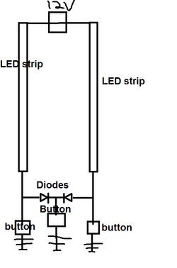
The trick is to use a pair of diodes to make sure that the two strips can't ground (or supply) to any switch other than your LightBothStrips switch.
Below is how I'd wire it if you're switching ground.
If you're switching supply the diodes need to point the other direction (allowing voltage flow away from the switch but not towards it) and the switches need to be up top of course.

The downside to this scheme is that the diodes will eat 0.7v or so, so the LEDs will be a touch dimmer when the LightBothStrips button is used.

LED strips.png

(Yay for MSPaint...)


EDIT:
Conveniently if you're switching the grounds like the above diagram, every 80+ bronze or lower PSU on the planet has at least three diode packs wired just like that, and they're schottkys so it's more like a 0.3v drop too!
Alternatively, digikey has 'em: http://www.digikey.com/product-detail/en/SBR10100CT/SBR10100CTDI-ND/1531944
Common anode (for use on the voltage supply side) cost rather more, but exist: http://www.digikey.com/product-detail/en/FEP16DTA/FEP16DTAFS-ND/1055216
Much higher voltage drop, don't know why nobody makes 'em in schottky flavor. Not a large enough market maybe.
 
Last edited:
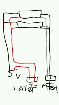
Well, I'm thoroughly confused again lol I'm not sure if I explained it sufficiently so I'll include a couple of drawings. Pardon the quality...

The first one is of what the strips came as, each connected to a 5V source and with a momentary switch to control the flashing pattern.
1352070628287.jpg

The second is what I'd like to accomplish with a latching switch turning them on and off and a second momentary switch to cycle through the modes.
1352070911438.jpg

Edit: The LEDs in the switches have their own terminals which I will be connecting to a 12V source.
 
Back