• Welcome to Overclockers Forums! Join us to reply in threads, receive reduced ads, and to customize your site experience!
Peltier (TEC) + Liquid Cooling Project

Overclockers is supported by our readers. When you click a link to make a purchase, we may earn a commission. Learn More.
ok, so the water heats the hot side, and the fan cools the cold side?

Or are you trying to cool off both sides?
 
That fan and heatsink are about right for cooling a ~15w load at most, possibly less.
You won't be cooling the water with it at any great rate.
Your best bet using that fan/heatsink would be to run ~7.5 to 10w of electrical power through the TEC, in turn pulling 7.5-5w of heat out of the water.
The issue with that plan though is that the water pump may well use the water for cooling, and if it does it'll be putting more heat into the water than the TEC is pulling out.
Even if it's not, 7.5w of cooling isn't going to get the water very far under ambient. Not without a tremendous amount of insulation on all the hoses and WB and such.

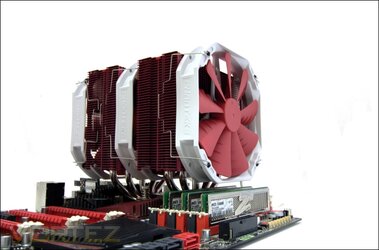
If you want to move a decent amount of heat out of the water via the TEC you're going to need a heatsink more along these lines:

phanteks ph tc14pe cooler final shot.jpg

Big.


You can do some thermodynamics equations with the surface area of your loop and the thermal conductivity of all the bits in it to figure out how many degrees below ambient a given amount of heat removal will give you. I do not know these calculations, but I know they exist.

My experience has been that with a TEC you need a lot of cooling on the hot side if you want to cool things off.
If you aren't aiming to get the cold side as cold as possible (which you're not) you're going to need exact control over the power draw. This is not something that diodes in series can give you. You need active control.
What I would do is use a microcontroller with a differential ADC and PWM outputs.
First regulate the voltage (active regulation, not diodes in series) being applied to the TEC to its max rated spec. No more.
Most 40x40mm TECs are rated for 15v, feel free to use the "raw" 12v out of a computer PSU. That'll be fine. Key is, it must be equal to or lower than the TEC's rated voltage, and it must not change in a meaningful way with load. This is where diodes fail for regulation, their voltage drop changes significantly with load.

Put a 0.1 ohm resistor in series with the TEC. Put a 10-47µF capacitor in parallel with that resistor.
Wire the microcontroller's ADC in parallel as well, - side to the TEC side of the resistor/cap, + side to the power supply side of the resistor/cap.
This, plus ohms law, gives you the average current flowing through the resistor, and hence the current flowing through the tec.
Combined with the active voltage regulation you can now calculate the wattage.
The microcontroller can PWM the ground side of the TEC (via MOSFET) for current/wattage control.

If you don't have access to a MCU with a differential ADC you can either buy a differential ADC chip that speaks i2c or SPI and have the microcontroller talk to that, or buy an op-amp and wire it to amplify the voltage across that resistor and give it a ground reference.
 
That fan and heatsink are about right for cooling a ~15w load at most, possibly less.
You won't be cooling the water with it at any great rate.
Your best bet using that fan/heatsink would be to run ~7.5 to 10w of electrical power through the TEC, in turn pulling 7.5-5w of heat out of the water.
The issue with that plan though is that the water pump may well use the water for cooling, and if it does it'll be putting more heat into the water than the TEC is pulling out.
Even if it's not, 7.5w of cooling isn't going to get the water very far under ambient. Not without a tremendous amount of insulation on all the hoses and WB and such.

If you want to move a decent amount of heat out of the water via the TEC you're going to need a heatsink more along these lines:

View attachment 147860

Big.


You can do some thermodynamics equations with the surface area of your loop and the thermal conductivity of all the bits in it to figure out how many degrees below ambient a given amount of heat removal will give you. I do not know these calculations, but I know they exist.

My experience has been that with a TEC you need a lot of cooling on the hot side if you want to cool things off.
If you aren't aiming to get the cold side as cold as possible (which you're not) you're going to need exact control over the power draw. This is not something that diodes in series can give you. You need active control.
What I would do is use a microcontroller with a differential ADC and PWM outputs.
First regulate the voltage (active regulation, not diodes in series) being applied to the TEC to its max rated spec. No more.
Most 40x40mm TECs are rated for 15v, feel free to use the "raw" 12v out of a computer PSU. That'll be fine. Key is, it must be equal to or lower than the TEC's rated voltage, and it must not change in a meaningful way with load. This is where diodes fail for regulation, their voltage drop changes significantly with load.

Put a 0.1 ohm resistor in series with the TEC. Put a 10-47µF capacitor in parallel with that resistor.
Wire the microcontroller's ADC in parallel as well, - side to the TEC side of the resistor/cap, + side to the power supply side of the resistor/cap.
This, plus ohms law, gives you the average current flowing through the resistor, and hence the current flowing through the tec.
Combined with the active voltage regulation you can now calculate the wattage.
The microcontroller can PWM the ground side of the TEC (via MOSFET) for current/wattage control.

If you don't have access to a MCU with a differential ADC you can either buy a differential ADC chip that speaks i2c or SPI and have the microcontroller talk to that, or buy an op-amp and wire it to amplify the voltage across that resistor and give it a ground reference.

Thanks for the detailed response! If I need such a huge heatsink, it may have never been possible for me to consider inserting all the hardware within a infant mannequin's leg eh? I may just have to consider keeping everything external minus the blocks and tubes...

So while testing, I just want to see if cooling at all is possible (so as cold as possible is good for now...). And I don't have much circuitry experience so it may be difficult to get that MCU setup going.

Do you think an 80x80mm aluminum heatsink+fan setup will work? (The heatsink on the left compared to the current one I'm using on the right)

***Ideally I also want to get rid of the reservoir.. how can I get a T-line set up? Is it just a T-piece + extra line of tube + a plug at opening of extra tube?
 
Last edited:
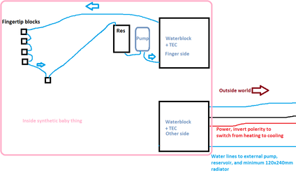
Here's what I'd do.
The TEC is a 40x40mm job, I would feed it 5v under the control of a microcontroller. No microcontroller = no way in hell it will maintain a given temperature heating or cooling. A PNP/NPN MOSFET H bridge will be required to switch between heating and cooling modes.
If 5v doesn't give enough heating/cooling, 12v should be used. This will make the H bridge design a bit more awkward, but still doable.

External cooling, with pump and radiator will be required, might as well run the TECs from out there too.

baby model testing heating cooling thing design pre-alpha.png

Please do note that none of the above has actually been tested by me.
I'm happy to go further into this and make/test an actual physical system, but at that point we're going to have to take a trip to the classified section and start talking money.
 
I no longer need heating (only need cooling), so no need for an H-bridge. The diagram above would involve two loops, correct? Why not keep things within a single loop?

An idea I have is having only tubes+fingertip blocks inside the baby ---> waterblock+TEC+heatsink joined unit ---> radiator ---> pump+res ---> back inside baby.

Also, is there a purpose for a microcontroller if I could just directly supply 5V?
 
Last edited:
If you just need cooling you can get rid of the H bridge, yeah.
You still need the MCU to control how cold the thing gets, without it you're either going to end up with only a small drop in temperature or freezing the water in the loop.

The diagram above has two loops for reasons of quick temperature changes, the more water is in the loop the longer it will take the change its temperature with a given TEC wattage.
If it's OK if the temp change takes a while, you could do one loop on the cold side of the TEC and a big air heatsink on the hot side.
Running the TEC at 12v you'd probably be looking at somewhere between 10 and 30 minutes to drop from 35°c to 25°c. At 5v, significantly longer.
Of course, without a heating mode the baby model thing will never go above room temperature.
 
How essential is the radiator? With a bigger heatsink+fan, I do seem to be able to cool to a certain degree (need to do more testing over a longer period of time though). Will the radiator make the cooling a lot quicker?
 
You don't want a radiator on the loop that has the fingertips.
If you're using air cooling on the hot side of the tec no radiators are needed anywhere.
 
If I use two loops, I'll have a radiator in the hot-side loop instead of a heatsink sitting on top of the hot side of the TEC? This cooling is way too slow, so I'm going to give 2 loops a try.
 
How hot is the air heatsink getting?
If it's not hot to the touch more cooling on the TEC hot side will not change the cooling rate of the TEC.
Given decent hot side temps, only more wattage through the TEC will increase cooling power.

If you're running a 130w 12V TEC at full power, that is about 65w of cooling, or ~221BTU/hr of energy transfer.
One BTU is the amount of energy it takes to heat or cool one gallon of water by 1°F.
So in theory you could cool one gallon of water by 3.68°F per minute.
Running that same TEC at 5V results in ~11 watts of cooling, or 37.x BTU/hr and less than a degree per minute per gallon.

The air heatsink doesn't get all that hot, so maybe I do need more wattage. I've got about 4-5oz of water in the loop (128 oz in a gallon) and I'm supplying 10V/3A. Considering how little water is in the loop, shouldn't the cooling be MUCH faster? The loop also seems to cap at a certain temperature (doesn't get that cold)...

Just tried supplying 12V/4A, and the heatsink was heating up a lot faster than it was with 10V/3A.. might have to get an ever bigger heatsink as well as a stronger TEC.. quite some trial and error here
 
Last edited:
How hot is not all that hot? Warm to the touch? 10°C above ambient? 30°C above ambient?
How do you know the 3 amp part? Do you have a current sensor on it? A limiting resistor?

10v * 3a = 30w, so about 15w of heat movement from the TEC. Keep in mind that the ambient environment is warming the cold side and cold side loop the moment it goes under the ambient temp. This will slow down the cooling process and impose a temperature floor as well.
For calculation purposes don't forget the copper in the block(s) and the tubing, or that the pump is almost certainly dumping at least a few watts of heat into the loop.
 
Warm to the touch - don't have a temperature reading unfortunately. I'm using a DC power supply where I can control voltage supplied and see the current reading.
 
More tec power is probably the answer then. Start cranking the voltage up and see what happens. Do be sure to stay under the maximum voltage rating of the tec of course.
 
More tec power is probably the answer then. Start cranking the voltage up and see what happens. Do be sure to stay under the maximum voltage rating of the tec of course.

Do I need to stay under the max wattage rating or max voltage rating, or both?

Ex. Can I supply more than 12V to this? (What is Umax?)
(Voltage(V): 12V Umax (V): 15.4V Imax (A): 6A
QMax (W) : 92W)

Also, what effect does the difference in wattage make between the above and this?
(Voltage(V): 12V Umax (V): 15.4V Imax (A): 10A
QMax (W) : 154W)

They have the same V and Umax, but different Imax and therefore Qmax. I don't have control over the current I can supply, but if I supply the same voltage to both of them, will more power be supplied to the latter to reach a higher Qmax?

----------------
I'm using this TEC (Qmax: 58-65W) at the moment and wondering if the above TECs will do a better job.
 
You need to stay under the Qmax most importantly. At Qmax it will draw its max rated watts and move the most heat.
However it is more efficient at moving heat if you run it at a bit lower voltage, 12v or 13v rather than 15v for instance. TECs are weird. They're more efficient the lower the wattage applied, but of course they also can move less heat at a lower wattage.

You'll get more cooling with a more powerful TEC, assuming you can keep the hot side cool.

The TEC you're using right now has odd specs, I suspect they are fake specs. That is an issue with any Chinese sourced part of course, there's no guarantee that the others are more accurate. The others do match at least.
 
Will the other TECs with a higher Qmax be supplied with more wattage when I supply the same voltage to each of them (12V)?
 
Last edited:
If you give the tec Umax voltage it will draw Imax current, resulting in Qmax watts.
That, of course, assumes all the numbers are real.
 
If you give the tec Umax voltage it will draw Imax current, resulting in Qmax watts.
That, of course, assumes all the numbers are real.

Thanks, that explains it. Do you think these other 12V TECs will make a significant difference in cooling? Or would it be a better idea to look for TECs with much higher voltage ratings? I'm surprised at how inefficient these things are considering that they're supposed to be great for CPU cooling.

I'm thinking that maybe my heatsink is still not good enough. (4x4x1 inch aluminum heatsink + a fan sitting on top of it).

Edit: I'm pretty certain the heatsink does its job good enough (the waterblock actually feels COLD to the touch when I turn off the pump). So now the pump is putting too much heat into the loop OR water is just not all that great at conducting heat energy. Would a liquid coolant make that much of a difference?
 
Last edited:
Back