• Welcome to Overclockers Forums! Join us to reply in threads, receive reduced ads, and to customize your site experience!

The Big Black Beast - My Prometeia/Peltier Cooled Case Project

Overclockers is supported by our readers. When you click a link to make a purchase, we may earn a commission. Learn More.
Klimpen

The voltage meter sounds like a great idea but I would look for some digital display.
I mean if you read out VCORE you vould like three or four digits precision. You would need to know the difference from 1.550V and 1.575V and I doubt your analogue can make that clear *smile*.

That's certainly true, good point :). For now, I intend to label the multimeter faceplate with smaller incremental markers around where VCORE, and VDIMM will be read out (~1.4V-1.9V, and 3.2V-3.9V). I like digital displays, but I despise batteries. If I can't find a 12V multimeter I'll probably just stick with this one.

I still think a transparent door would look awesome but I get you when you say "impossible". Isn't there any way to use some akrylic in the door? Just a small small column like 2 inch wide??

I've got some really thin and bendable plexiglass type stuff, but even it is too thick :-/. You see, I can easily make a window cutout in the door, but can think of no way to mount the plexi inside of the door without making the door too thick. As it is, the switches on one of my Rheos is touching the back of the door panel.

I could maybe do a small window shape in the top of the door (where the B3 VControl panel will be), and do some plasticard work on the bottom half? I'm still brainstorming :)
 
felinusz said:
That's certainly true, good point :). For now, I intend to label the multimeter faceplate with smaller incremental markers around where VCORE, and VDIMM will be read out (~1.4V-1.9V, and 3.2V-3.9V). I like digital displays, but I despise batteries. If I can't find a 12V multimeter I'll probably just stick with this one.


I've got some really thin and bendable plexiglass type stuff, but even it is too thick :-/. You see, I can easily make a window cutout in the door, but can think of no way to mount the plexi inside of the door without making the door too thick. As it is, the switches on one of my Rheos is touching the back of the door panel.

I could maybe do a small window shape in the top of the door (where the B3 VControl panel will be), and do some plasticard work on the bottom half? I'm still brainstorming :)

This is really looking great!!!! I am building a project similar but not quite the same. Same Materials but different case. I am really enjoying reading this thread. As far as the 12V DMM goes. Just get a Zener Diode and step the voltage down to 9V. You could also use a resistor but for this application I would trust a Zener more.
 
I am sorry for the lack of recent updates - with the case more or less completed I've been spending a lot of my time overclocking the stuff inside of it :).

Some bad news - due to a completely random leak, my Mach II has died before I even got to properly implement it. However, I am mailing it to Gkiing of Xtremesystems for a repair and total overhaul. It looks like I'll be having the heavily modified and tweaked out Uber Mach II unit that this project originally called for after all... such is fate :).

I am having the unit:

~ Repaired
~ Reinsulated
~ Regassed with R507 (Unfortunately Gkiing does not have access to small amounts of R402 - R507 is slightly worse than R402 for temperatures as I mentioned way back in the project outlines, but is still a very signifigant improvement over R134 :-/)
~ Captube replacement
~ Much larger condensor installed
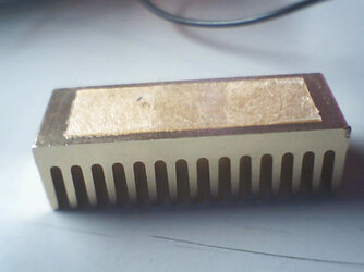
~ chilly1 evaporator installed for easier mounting
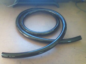
~ More flexible and durable flex-line installed

My two goals with these modifications are greater ease of use for frequent evap mounts and removals, as well as a much higher heatload capacity to futureproof the unit.

For a dual-core processor down the road, or even for the next generation of processors way down the road, a high heatload capacity will be essential if this unit is to stay useful. The compressor is sufficiently powerful to handle a very hot processor, the charge just needs to be properly tweaked for capacity. Temperatures will intentionally be compromised slightly in order to accomplish this - the modified unit will provide slightly better temperatures than a stock Mach II, but at a MUCH higher heatload capacity. My philosophy on this is that ~5 degrees celcius isn't going to accomplish much when you're already running at, say, around -40 degrees celcius; -40C with 240W of capacity is much more useful to me than -45C with 190W of capacity. These numbers are entirely innaccurate and for example only - I will have specific numbers as soon as the unit gets to British Columbia.

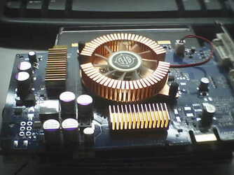
All of that said, I have a major update - the Big Black Beast now has peltiered GPU watercooling.


pwnt by pat
Get that radiator in there since you have it and all now....

fool

Who's a fool!? Watch your step brar' ;) :D

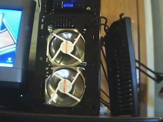
The radiator/shrouds are my dream setup - this thing is fittingly a beast and a half of a radiator. Specifically for the Big Black beast project, Pwnt by Pat made me two custom fibreglass shrouds for a Fedco 2-342 single pass radiator, which (according to the plan) is now cooling a 172W peltier on my video card. Pat has put a lot of effort and workmanship into these shrouds - and the result is fantastic.

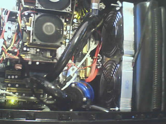
The custom radiator and the rest of the "Hotblack Watercooling" (the name will make sense in a minute ;)) is now installed and operational.

Let's take a look at the specifics of the watercooling circuit I've put together.

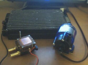
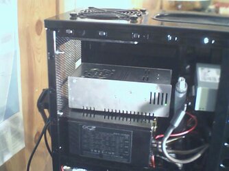
The pump I am using is a 12V Swiftech MCP600, my favourite waterpump for its low noise, great pressure, small size, and 12V operation. For the video card I am using a Danger Den Maze4-1 waterblock, with a 172W/24V peltier. The Peltier PSU I am using is a 24V/240W Meanwell unit. The Radiator is Pat's beastly Fedco 2-342 single pass radiator - low restriction, excellent heat capacity, and room for four 120mm fans with the fibreglass shrouds.

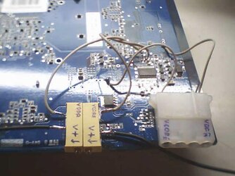
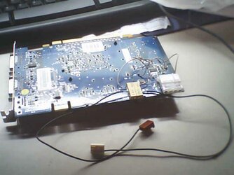
Here are the parts layed out:
 

Attachments

  • parts.JPG
    parts.JPG
    23.2 KB · Views: 775
Last edited:
Now, the special and attractive part of this watercooling circuit is the tubing I picked up.

It's Tygon tubing, but a special chemical-resistant version. I didn't pick it for it's chemical tolerences, rather for its colour... black. Hey, how could I resist black tygon? This stuff has the same flex radius as traditional Tygon, but seems a little stiffer and 'grippier' to me.

I must aplogize for the picture quality, unfortunately I'm stuck using a cheap webcamera.
 

Attachments

  • R-3400.JPG
    R-3400.JPG
    24.2 KB · Views: 731
Here's a shot of the watercooling loop installed in the Beast. The T-Line is clear, so that I can see water levels, and gauge whether the loop has completely bled or not - the R-3400 Tygon tubing is opaque.

I should mention, that the wiring is not done yet, and is still somewhat messy looking :). I still need to find some black coloured removeable wire clamps to use for wire management.
 

Attachments

  • Loop.jpg
    Loop.jpg
    40.6 KB · Views: 922
Last edited:
The Radiator is mounted in the front of the case, with the four 120mm AOC Evercool Aluminum fans positioned to blow exhaust through the front of the computer case, as outlined in the airflow plan for this project.

This is done so that all of the hot air coming off of the radiator (a 172W peltier cooling an aggressively overclocked/overvolted video card dumps a lot of heat into your water!) is exhausted out of the case. The two 120mm fans mounted in the case sidepanel, and the two 80mm fans mounted in the case rear compensate for this, and provide an efficient "reverse airflow" wind-tunnel through the computer case, putting cool air in through the rear and side of the case, exhausting hot air out the front and top. Unconventional, but it seems to work nicely.

Here's a shot of the radiator mount in the front of the case - Not perfectly clean, but completely invisible with the front-bezel installed :)
 

Attachments

  • mount.jpg
    mount.jpg
    37.3 KB · Views: 727
Last edited:
The dedicated 24V Meanwell PSU is installed in the topo half of the case, the operational LED conveniently visible through the upper side-panel window for safety (I can see if it stops working and hopefully save my video card from a fiery death ;)). It sits directly above the computer PSU, attached with a piece of velcro. Above the PSU a 38mm thick 120mm Panaflo M1A fan blows exhaust out the top of the case. Working with this 120mm fan, the Meanwell has a silent little fan integrated into it which blows directly upwards. The Meanwell unit's fan turns on and off depending on the Meanwell's operating temperature.

Surprisingly, the air coming out of the top of the case is very warm.
 

Attachments

  • upperflow.JPG
    upperflow.JPG
    34.4 KB · Views: 721
Very nice gpu loop. That radiator/shroud looks awesome. Maybe get some foamy window-sealing stuff for around the fans to further increase efficency of the radiator by eliminating leaks?
 
It's pretty darn close to airtight already, I can't feel any 'leaking' airflow with my hands all the way around the radiator :).

With the mounting hardware tightened up (I made the mounting hardware out of a single threaded rod that I cut into four pieces, with 8 wingnuts) the fans and shrouds are quite tight and very snug - you did a very good job fitting these shrouds properly.
 
Love how you planned out the airflow through your case.

Good job with the cuts for the windows and fans as well.
 
Gkiing of XtremeSystems has begun the modification work to the Mach II, and has also started a project log of the mods over on XS :).

Here is GKiing's thread on XS, with pictures of his modification work on my unit thus far: http://xtremesystems.org/forums/showthread.php?t=69392


Further updates, results, and pictures will follow when the unit makes it's way back over here from B.C :)
 
Got the Mach II back a few days ago, and will hopefully be hooking it up soon. It's been regassed with R507, tuned to 220W/~-40C and has been outfitted with a chilly1 evap.

I'm waiting for the evap's mounting enclosure which is on it's way, soon to be put to use :). Pictures, and hopefully results, should be on their way.
 
As a matter of fact, yes, there are! :D

I've had alot of spare time recently, and have begun putting the machine back together.

For those of you who don't know, the Beast has seen some pretty hard times recently;

The Mach II got hooked up for about two weeks, but with very poor results (I think I know why though :)), and then broke again (a faulty thermistor) - it hasn't been in use since. My X700 Pro was fried in a careless accident, and the peltiered watercooling has not been in use since.


SO, the goal now is to get everything put together nicely, so I can post some pics of the full system actually running, in this thread :)


To start with, I began work on my "new" video card, a BFG 6600 GT OC that is replacing my old X700. By today's standards it's fairly low end video, but I'm fine with that because I'm so poor :).

First, I voltmodified the card - it's going under the peltier after all, and will be needing some overvoltage to be made the most of.
 

Attachments

  • vmod1.JPG
    vmod1.JPG
    35 KB · Views: 476
After using this card and voltmodding it, I'm an nVidia convert :)

The 2D/3D voltage supply nVIdia uses on almost all their hardware is an excellent feature - something ATi didn't implement with the X700, but really should have. Also, the 2.0ns memory on THIS card overclocks to 630 MHz with stock voltages, where the X700's 2.0ns RAM didn't make it past ~560... whats up with that eh? :eh?:

The voltmods for this card were easy to say the least, it's almost like nVidia intended for them to be simple. All the hotpoints and readpoints are actually little 'holes' (solder points for caps) on the pcb. Voltmodding the card was as simple as sticking the wire into each hole, and applying a bit of solder.
 

Attachments

  • vmod2.JPG
    vmod2.JPG
    31 KB · Views: 471
Next, I decided to replace the stock RAMsinks BFG provided with this card.

While it was thoughtful of BFG to give me RAMsinks for free, they did quite a poor job of attaching them... with thermal tape that didn't even make contact with the entire memory IC!

Here are the stock RAMsinks on the card. Full copper, and nicely sized, but just not enough.
 

Attachments

  • cardstock.jpg
    cardstock.jpg
    40.8 KB · Views: 464
I removed the stock RAMsinks by very carefully wiggling each heatsink back and forth, untill it popped off. Took about 5 minutes per heatsink, I didn't want to pull off a memory IC (which is remarkeably easy...) !

Thermal tape... ewwwww.
 

Attachments

  • stockramsink.jpg
    stockramsink.jpg
    31.4 KB · Views: 462
Back