Hello everyone, thank you for taking the time out of your day to read my project log.
First off, let me clarify the title. Currently I do not have a name for this project so the title that I choose was the easiest way to describe this project with the least amount of words possible.
Second, This is going to be a long term work in progress. I only have a select number of weekends that I can work on this project. Reason being, is the computer that is residing on this project is my workstation. During the week I need my workstation to be functional so I can do my testing for school on it. I also don't have a lot of room on my desk left on my desk for hardware from the workstation to be laying around.
Alright, Here is the reason for the project in the first place. I already had a custom computer case that I built to house my workstation in and it was working just fine. (Build thread of the case http://www.overclockers.com/forums/showthread.php?t=660964 Build thread of adding the water cooling to it http://www.overclockers.com/forums/showthread.php?t=691497) However, I moved locations and that forced me to re-do the layout of my room. With the way I designed the old case to work on my desk with it place on the end and the new room, the location of the computer was smack dab in the middle of my room. This created two problems, one the computer took up a lot of visual real estate in my room with it being right in the middle. Second, the radiator was now sticking out in the walkway of my room. If you were not careful you could get your shirt caught up on the radiator as you were moving around the room and pull the computer off the desk.
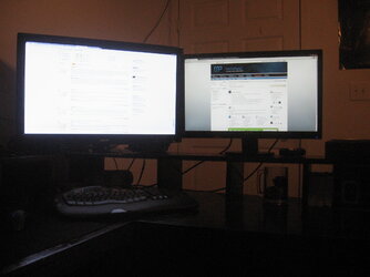
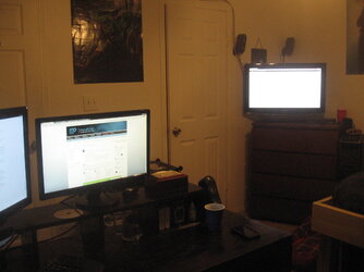
So I sat for a while thinking of how I could fix these two issues. First I came up with the idea of building a new case that was symmetrical to the original so that it would work on the other side of my desk. This fixed the issue of the computer being in the middle of the room but it still left the issue of the radiator sticking out into the walkway of my room as my closet door lines up right on the edge of my desk on that side. The layout of my room is not ideal to say the least because of the position of my bed and desk, but this was the only option I had to work with due to the positions of the three doors in my room. So, I kept thinking a little harder. I then came up with a solution to fix my current problems and to solve any future problems as easily as possible. The desk, no matter what room it goes in, will always have a side up against a wall. I typically run three monitors (2 connected to the workstation and 1 connected to 2 other computers via kvm switch) My side two monitors will never see the size bigger then 23in and my main monitor is bigger then my side monitors. Right now my main is a 32in lcd tv but I want to downsize to a 27in monitor, I feel the 32in is just to big for how close it is to my face.. Doing this setup creates a nice visual box on the wall that is roughly 2 and a half feet wide, plenty of space for me to mount the computer to. This fixes all my problems, it moves the computer out of the middle of my room and positions the radiator in a better location that wont allow it to get hung up on. Also since my desk is symmetrical(5'X5' corner desk that I made), I wont run into the problem of not having any room for it because it is always going to have that 2 and a half foot section of wall to mount it to, on both sides. Just depends on what side the wall is on.

For some reason I cant sit on one piece of hardware (cpu/gpu) for longer then a year without the urge to upgrade it for no apparent reason . Because of this, I need a solution that wont hinder me when doing the upgrades. This requires the entire motherboard and all the hardware that is physically attached to the motherboard to be easily removable just like a bench test case. As for the other hardware, they are going to be mounted in a way that aids the most in ease of use. The power buttons(main power, led lights), fan controller, and disk drive are going to be located on the bottom of the mount. This puts them in arms reach right above the side monitor.
Since this is a long term project, I'm going to be spending quite a bit of time working on the small details. I don't want to spend all this time and create something that is sub-par. With that being said, I want this project to have the same quality that a show piece would have. There will be blue LED lighting incorporated in this build but they are going to be used for accents and a little bit of wow factor.
Goals:
1. Ability for easy motherboard/cpu/gpu/ram exchanges.
2. Wall mounted
3. Unique
4. Artistic (as much as can be done with a computer... lol)
Well, that is the plan anyhow lol.... Lets see how will it turns out.
****Lack of pictures on the first sort of progress****
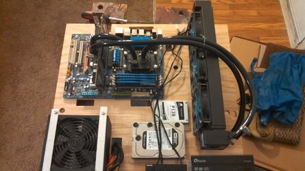
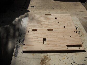
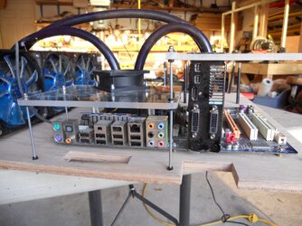
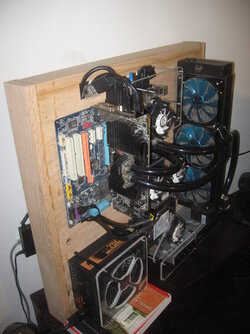
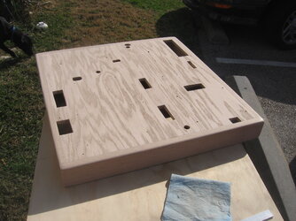
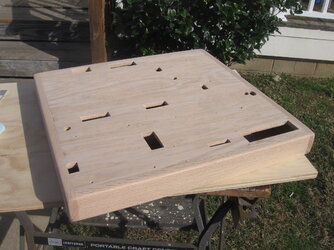
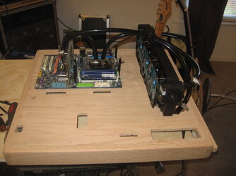
First off I started with the base board. A 2'x2' piece of 1/2in red oak from the local hardware store. I found out that I could layout all the hardware needed to fit on the face of the base board inside a 21"x 22" rectangle. I then cut down the 2'x2' oak to fit my required rectangle. I Decided I wanted my motherboard to be located at the top left and for my radiator/pump to be located on the top right. After measuring a couple of times to make sure everything was straight, I drilled holes to mount the motherboard standoffs and the piece of 1in angle aluminum used to mount my radiator. I then cut out some holes in the base board so that I can run wires through them. This brings us to the first picture that I have of this project..... well I thought I had a picture of this stage of the project... The picture I was thinking about doesn't show the computer in the picture at all, it is right outside of the edge of the picture .
.
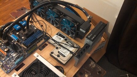
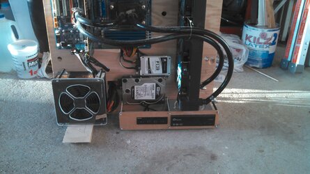
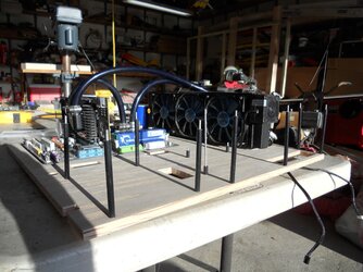
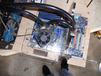
So the project sat propped up on the side of my desk during this stage (main hardware and water cooling mounted on the base board with everything else in a wired mess behind the board) for a couple of weeks. Quite similar to the current pictures, so you will see what I'm talking about pretty soon.
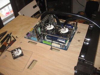
This brings us to the present. Today was a pretty good day to work on the project. Started off nice and sunny, perfect to do some wood work outsides. This allowed me to make the holes for the water cooling tubes to go through the base board. I put two next to the motherboard, one for inlet and one for outlet kinda on opposite ends of the motherboard. Two more are located on the other side of the radiator. My plan is to have quick disconnects located next to the motherboard so that I can satisfy my first goal for the build. By the mid afternoon we had a pretty severe thunderstorm come in that lasted for a good five hours. I didn't let this stop me for I'm a man and what do good men do when they have the house all to themselves with no garage to go to to seek shelter from the elements? That is right, living room gets used as a temporarily garage. Let me clarify something real quick, I'm a college student with two other roommates and a dog, the living room doesn't stay as clean as a wife would like it to be at times. Plus I don't have a wife to tell me not to use the inside of the house as a work place. So setup the work area, turn the jams up to 11 and proceed to make a mess.


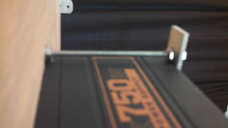
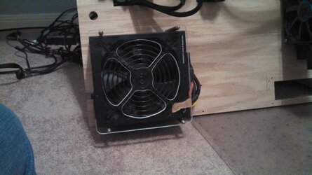
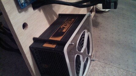
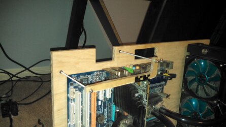
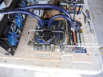
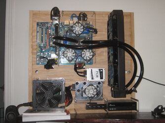
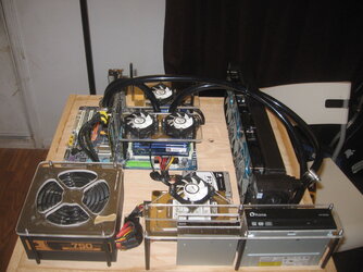
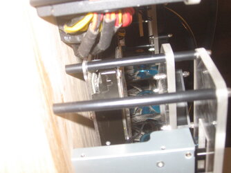
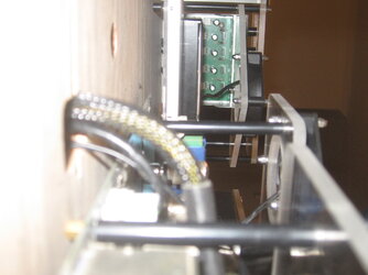
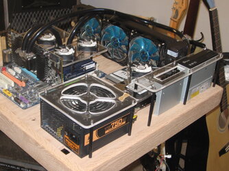
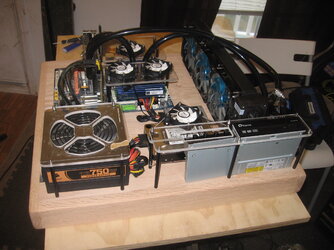
As I was inside, I decided I would do a little bit of sanding to erase some of my pencil markings and to clean up the cutouts I made for the wires. I also decided it was a good time to place the PSU in its new home. To do this I used a 1/2in piece of aluminum flat bar cut into two pieces. I then used some all thread and a of couple washers and nuts to create a method to hold the PSU to the baseboard. It isn't completed yet but it does give the PSU a new location other then on my desk. I will end up sleeving the all thread with some aluminum pipe so that you see a smooth bar instead of the threads. I also still need to trim up the aluminum flat bars a little bit, I ground down the sharp edges from cutting but I want to round off the ends. I also messed up on one of the bars, the hole I drilled on one of the ends didn't come out centered and it's been bugging me lol

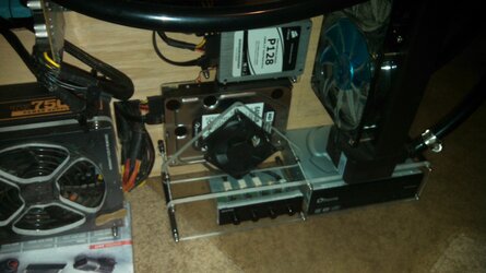
It is going to sit like the next pictures until the next time I can shutdown the computer and work on it.


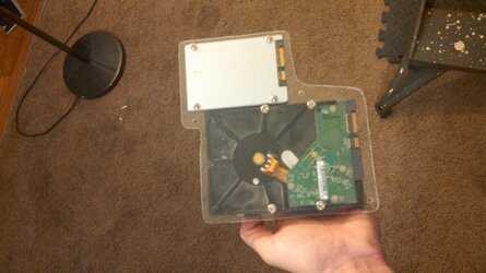
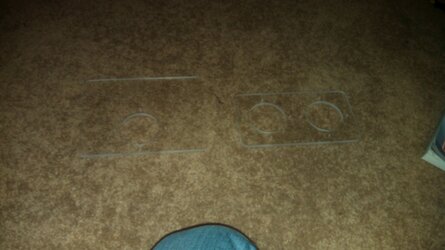
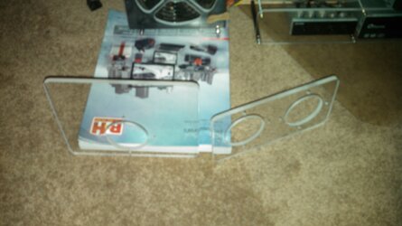
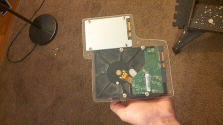
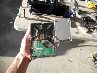
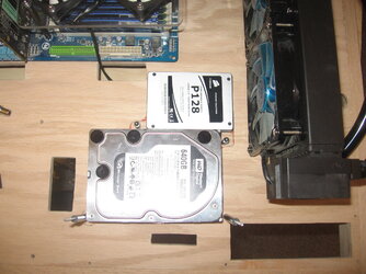
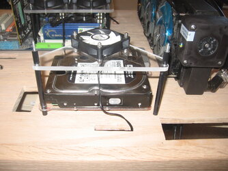
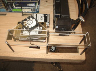
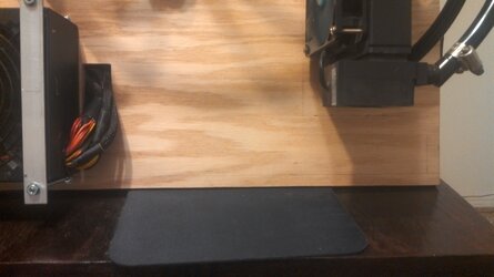
The next endeavor is going to involve mounting the disk drive. It is going to go underneath the radiator/pump on the bottom right.

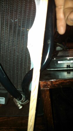
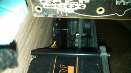
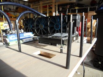
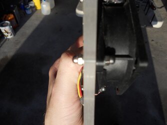
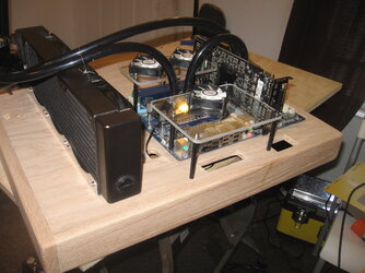
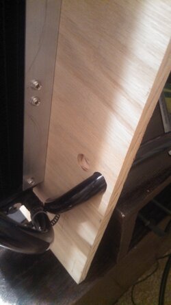
This picture shows you how the inlet of the radiator is going to work with its hole through the base board. I still need to sand down the hole some more to make it more formed for the tube to go through it like that. As it is sitting now it doesn't kink but like I said earlier, I'm going to be spending a lot of time doing the small details to make everything near as perfect as I can achieve for this project.

First off, let me clarify the title. Currently I do not have a name for this project so the title that I choose was the easiest way to describe this project with the least amount of words possible.
Second, This is going to be a long term work in progress. I only have a select number of weekends that I can work on this project. Reason being, is the computer that is residing on this project is my workstation. During the week I need my workstation to be functional so I can do my testing for school on it. I also don't have a lot of room on my desk left on my desk for hardware from the workstation to be laying around.
Alright, Here is the reason for the project in the first place. I already had a custom computer case that I built to house my workstation in and it was working just fine. (Build thread of the case http://www.overclockers.com/forums/showthread.php?t=660964 Build thread of adding the water cooling to it http://www.overclockers.com/forums/showthread.php?t=691497) However, I moved locations and that forced me to re-do the layout of my room. With the way I designed the old case to work on my desk with it place on the end and the new room, the location of the computer was smack dab in the middle of my room. This created two problems, one the computer took up a lot of visual real estate in my room with it being right in the middle. Second, the radiator was now sticking out in the walkway of my room. If you were not careful you could get your shirt caught up on the radiator as you were moving around the room and pull the computer off the desk.
So I sat for a while thinking of how I could fix these two issues. First I came up with the idea of building a new case that was symmetrical to the original so that it would work on the other side of my desk. This fixed the issue of the computer being in the middle of the room but it still left the issue of the radiator sticking out into the walkway of my room as my closet door lines up right on the edge of my desk on that side. The layout of my room is not ideal to say the least because of the position of my bed and desk, but this was the only option I had to work with due to the positions of the three doors in my room. So, I kept thinking a little harder. I then came up with a solution to fix my current problems and to solve any future problems as easily as possible. The desk, no matter what room it goes in, will always have a side up against a wall. I typically run three monitors (2 connected to the workstation and 1 connected to 2 other computers via kvm switch) My side two monitors will never see the size bigger then 23in and my main monitor is bigger then my side monitors. Right now my main is a 32in lcd tv but I want to downsize to a 27in monitor, I feel the 32in is just to big for how close it is to my face.. Doing this setup creates a nice visual box on the wall that is roughly 2 and a half feet wide, plenty of space for me to mount the computer to. This fixes all my problems, it moves the computer out of the middle of my room and positions the radiator in a better location that wont allow it to get hung up on. Also since my desk is symmetrical(5'X5' corner desk that I made), I wont run into the problem of not having any room for it because it is always going to have that 2 and a half foot section of wall to mount it to, on both sides. Just depends on what side the wall is on.
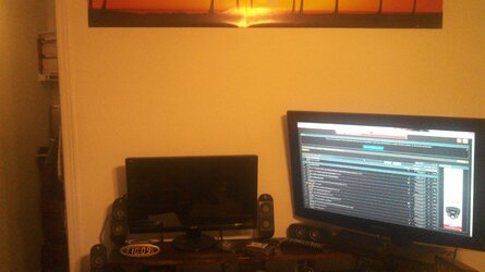
For some reason I cant sit on one piece of hardware (cpu/gpu) for longer then a year without the urge to upgrade it for no apparent reason
Since this is a long term project, I'm going to be spending quite a bit of time working on the small details. I don't want to spend all this time and create something that is sub-par. With that being said, I want this project to have the same quality that a show piece would have. There will be blue LED lighting incorporated in this build but they are going to be used for accents and a little bit of wow factor.
Goals:
1. Ability for easy motherboard/cpu/gpu/ram exchanges.
2. Wall mounted
3. Unique
4. Artistic (as much as can be done with a computer... lol)
Well, that is the plan anyhow lol.... Lets see how will it turns out.
****Lack of pictures on the first sort of progress****
First off I started with the base board. A 2'x2' piece of 1/2in red oak from the local hardware store. I found out that I could layout all the hardware needed to fit on the face of the base board inside a 21"x 22" rectangle. I then cut down the 2'x2' oak to fit my required rectangle. I Decided I wanted my motherboard to be located at the top left and for my radiator/pump to be located on the top right. After measuring a couple of times to make sure everything was straight, I drilled holes to mount the motherboard standoffs and the piece of 1in angle aluminum used to mount my radiator. I then cut out some holes in the base board so that I can run wires through them. This brings us to the first picture that I have of this project..... well I thought I had a picture of this stage of the project... The picture I was thinking about doesn't show the computer in the picture at all, it is right outside of the edge of the picture
 .
. So the project sat propped up on the side of my desk during this stage (main hardware and water cooling mounted on the base board with everything else in a wired mess behind the board) for a couple of weeks. Quite similar to the current pictures, so you will see what I'm talking about pretty soon.
This brings us to the present. Today was a pretty good day to work on the project. Started off nice and sunny, perfect to do some wood work outsides. This allowed me to make the holes for the water cooling tubes to go through the base board. I put two next to the motherboard, one for inlet and one for outlet kinda on opposite ends of the motherboard. Two more are located on the other side of the radiator. My plan is to have quick disconnects located next to the motherboard so that I can satisfy my first goal for the build. By the mid afternoon we had a pretty severe thunderstorm come in that lasted for a good five hours. I didn't let this stop me for I'm a man and what do good men do when they have the house all to themselves with no garage to go to to seek shelter from the elements? That is right, living room gets used as a temporarily garage.
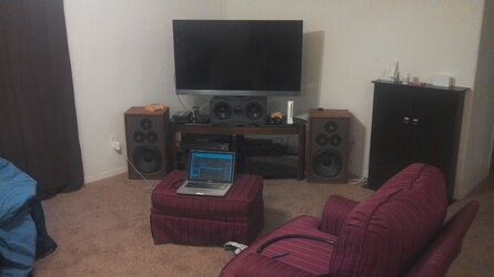
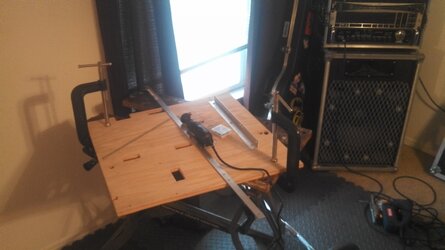
As I was inside, I decided I would do a little bit of sanding to erase some of my pencil markings and to clean up the cutouts I made for the wires. I also decided it was a good time to place the PSU in its new home. To do this I used a 1/2in piece of aluminum flat bar cut into two pieces. I then used some all thread and a of couple washers and nuts to create a method to hold the PSU to the baseboard. It isn't completed yet but it does give the PSU a new location other then on my desk. I will end up sleeving the all thread with some aluminum pipe so that you see a smooth bar instead of the threads. I also still need to trim up the aluminum flat bars a little bit, I ground down the sharp edges from cutting but I want to round off the ends. I also messed up on one of the bars, the hole I drilled on one of the ends didn't come out centered and it's been bugging me lol
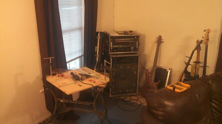
It is going to sit like the next pictures until the next time I can shutdown the computer and work on it.
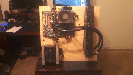
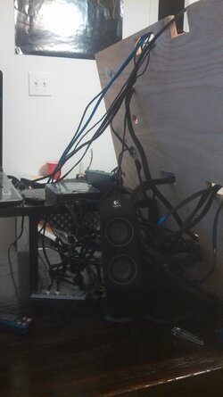
The next endeavor is going to involve mounting the disk drive. It is going to go underneath the radiator/pump on the bottom right.
This picture shows you how the inlet of the radiator is going to work with its hole through the base board. I still need to sand down the hole some more to make it more formed for the tube to go through it like that. As it is sitting now it doesn't kink but like I said earlier, I'm going to be spending a lot of time doing the small details to make everything near as perfect as I can achieve for this project.
Last edited:

