• Welcome to Overclockers Forums! Join us to reply in threads, receive reduced ads, and to customize your site experience!

LED wiring

Overclockers is supported by our readers. When you click a link to make a purchase, we may earn a commission. Learn More.
I made everything you see .... custom countertops ... cabinets and doors .. etc
 

Attachments

  • Glass Block Bath near complete 020 (Small).jpg
    Glass Block Bath near complete 020 (Small).jpg
    36.1 KB · Views: 155
The lighting behind the toilet is motion activated. It is an awesome feature and is stunning to look at. The pics don't do it justice.
 

Attachments

  • Glass Block Bath near complete 007 (Small).jpg
    Glass Block Bath near complete 007 (Small).jpg
    15.1 KB · Views: 157
Here is couple Quick-Time Video clips.

Before ...
Click Here WARNING 6.4MB

After ...
Click Here WARNING 7.9MB

Incase you hate Quick-Time as much as me ... HERE is a Windows Media Player Codec for Quick-Time. There are a few other goodies on that page too :>
 
I'm gonna send the before and after pics to a bunch of Kitchen & Bath magazines. I've seen them give away trips and MORE!

I think this one could be a winner :>
 
That looks really nice, I noticed in your second quicktime clip, it was labeled "not complete yet" what do you still have left to do?
 
Roofles said:
That looks really nice, I noticed in your second quicktime clip, it was labeled "not complete yet" what do you still have left to do?

I have to hang a few more cupboard doors ... install the 'rainhead' ... grout some baseboard tiles ... install the motion sensor for the lighting behind the toilet .... install glass panes in the door sidelights.

All those finishing things ... like door handles, etc ... seem to take FOREVER ... considering you never think of these things when quoting the whole job
:rolleyes:
 
Just curious .... What would you expect to pay for this kind of custom renovation?

I just want an idea of how much money I've lost :rolleyes:
 
does anyone know how to make a voltage controller? I was told that by putting the appropriate variable resistor on the middle leg of a regulator that it can be 'programmed' to supply the correct voltage.
Can anyone elabourate more?
 
Most modern regulators with fixed outputs (7812, 7912, 7805 etc.) pass a current of 10mA to ground for reference purposes. It is possible to vary the output voltage by 'fooling' the regulator as to the the exact zero point. This is done by adding a resistor in series between the ground of the regulator and real ground. A 1 ohm resistor will give additional voltage of 0.01 volts (1x10 mA or 0.01 amps) on the output. a 1K resistor will give additional 10 volts (1000 x 0.01).

Voltage regulation will suffer unless 0.1% or 0.5% tolerance resistors are used. Better to use LEDs (each red LED will add 1.6 volts), Diodes (each diode will add 0.7 volts), or other silicon which stays more constant than carbon resistors. For a particular fixed output a zener diode will also work.
 
Of course you have to respect the input voltage and the voltage differential. Most of these guys like to have at least 5 volts between input and output, so watch that as well.
 
Your power supply says 0-30V, isnt there a knob there that will let you change the voltage? Or is it not exact enough for your liking?

Also you could use a multimeter on the outputs and then adjust the voltage so you know you are getting exactly the voltage and current output you want/need.
 
Roofles said:
Your power supply says 0-30V, isnt there a knob there that will let you change the voltage? Or is it not exact enough for your liking?

Also you could use a multimeter on the outputs and then adjust the voltage so you know you are getting exactly the voltage and current output you want/need.

The unit you refer to is a testing unit. I intend to keep that. I am trying to figure a way to be able to use 9V OR 12V (unregulated .. so like 16V OR 19V) to power various numbers of LEDs. Pipe dream I guess.

Right now I have 19V @ 500ma ... I am looking for 3.6V @ 400ma
I have several 1W resistors in series and paralell to get 90R
I originally planed this for 9V (16V) and bought a 12V (19V) PSU by accident.

When I hooked up my testing unit, I had to dial it up to 16V (current didn't matter except when below 20ma x 20 LEDs = 400ma) but that reading changed alot when I opened the circuit .. it was maxed at 30V ... I think because the rope already has 1W resistors at the beginning adding up to 90R?
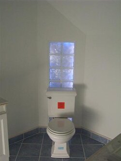
The picture with the toilet is the rope I'm havin trouble with.
So in order to light up my 5000mcd LED rope I calculated ...

Requirement: 3.6V @ 400ma
LED specs: 20 x 20ma = 400ma
Since I have already installed a 90R and the lights run perfect with 16V (measured while closed)
My new Requirement is 16V @ 400ma
I have a 19V @ 500ma supply. 19V @ 500 - 16V @ 400
So I need to add a resistor to remove 3V @ 100ma
That works out to 30Ohms using THE LAW.

I just don't want to fry my lights, since they are already installed in the wall. I did this a while ago and I'm not 100% sure about my previous calculations. So I would love a little clarification.

Sangram .. you seem to really know what your talking about. Perhaps you can steer me straight. I learn real quick :-/
 
Your basic problem is you are using resistors to drop the voltage. Resistors are very sensitive to current, and their resistance changes with the current draw, which can lead to inconsistency with the brightness of lights.

You need a supply which supplies the required current stably, and just couple the LEDs to it directly through a small resistance (22-47 ohms should usually be enough, just to protect the LEDs from catastrophic failure).

I don't know how you have them wired up, series or parallel. in your case parallel may be better because finding a faulty LED will be easier, you don't want to be poking around 100 LEDs to fins a faulty one.

Now let's say you want to power 20 LEDs. We will wire them in groups of two. Each group will have two LEDs wired in series, and the ten groups will be wired in parallel. For maximum brightness we will look at 25 mA through each LED. That means our current requirement is 25 x 10 = 250 mA. NOT 500 mA, as each series group will draw the same current as 1 LED.

Again for maximum brightness you are looking a voltage of about 3 volts. A small resistor will protect the LEDs from over voltage conditions, and yet not have so much drop as to create brightness fluctuations. This resistor, if it is 22 ohms, will have a drop of (.250/22) .01 volts or therabouts. As the current increases, the resistor will drop more voltage and in the case of a short circuit will probably blow, but will protect your LEDs.

Now we need a voltage source of 3 volts at 250 ma. Agreed?

Simple. We need one 7805 regulator. I believe you already have a source of power. A wall wart will also suffice. The 7805 regulator needs three silicon diodes (1N4001 or equivalent) connected to its output, in series.

7805 output ----|>|---|>|---|>|----^^^^^------ LEDs

That's it. The above circuit will supply (5-2.1) 2.9 volts, enough for the LEDs. 250 mA is not a very small current, so a small heatsink on the regulator may be nessecary.

The principle is simple - each silicon diode drop 0.7 volts. This is a fixed law, and is pretty accurate.

Now you can extrapolate this for any required current and voltage.

Idea is to keep the source voltage as tightly regulated as possible, and introduce resistors only as safety devices, not control devices.

Now, figure out how many LEDs you've got, and then, how you would like to wire them. I'm sorry if this is already covered somewhere else, but I couldn't find it after sifting through it. I assumed your last requirement is 16 volts/400ma, is that correct?

If it is not, then let me know what it is.

For 16Volts I would use the 12 volts regulator, 7812. Again a 1 amp wall wart will be fine for this application. Use one that puts out at least 24 volts DC into the circuit.

The combination we are looking for is 12+4 volts. We don't have a 4 volt accurate reference source, the closest is 5 volts. We need a 5 volts zener. The Zener should be connected with the anode (the side with the thin marking on the capsule) soldered to the middle leg of the 7812, and the cathode (the other end) to ground. The input pin of the 7812 connected to the wall wart, and the output to the LEDs. If the extra 1 volt is too much, just connect a diode in series (-0.7 volts). Now you're down to .3 volts excess. the 22 ohm resistor will absorb the difference. Just ensure it is a healthy 5 watt resistor, or connect 4 100 ohm, 1 watt resistors in parallel to be safe.

Greek?
 
What a klutz I am, your requirement is right in the beginning - 40 Blue LEDs in parallel.

Blue LED has forward voltage of 4 volts @ 30 mA. You will probably get full brightness @3.6 volts and 25 mA.

So it means 3.6 volts, 1 ampere. Use (5-1.4) 7805 with two silicon diodes on the output and one 22 ohm resistor, like I mentioned, except I had calculated for 20 red LEDs.

The 7805 will be operating at maximum current. Heatsink it with a huge mother, or use a series pass transistor like is shown in the diagrams on the page I sent. Also watch the wall wart. Needs to be at least 2 amps. Let's not clutter the thread, PM me if you need more help.
 
I made these acrylic blocks. They hold a clear acrylic shower curtain rod to the glass.

Flame polished
 

Attachments

  • New pics 005 (Small).jpg
    New pics 005 (Small).jpg
    44.6 KB · Views: 36
Back