-
Welcome to Overclockers Forums! Join us to reply in threads, receive reduced ads, and to customize your site experience!
You are using an out of date browser. It may not display this or other websites correctly.
You should upgrade or use an alternative browser.
You should upgrade or use an alternative browser.
FEATURED Building PWM Controller for 4 wires PWM fan
- Thread starter Brutal-Force
- Start date
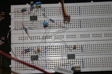
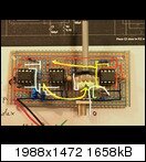
So, i think having planned too much. My first try to built a 0%-100% circuit failed. The fan is running at around 50%, and the poti's adjustment takes no effect on that.
 I've checked the circiut 3 times but cannot find any mistake.
  I will try the 1%-99%-circuit next.
Pictures for you:


Sorry for the quality, i'm afraid you cannot detect the failure from it.
edit: Hahaha sorry, by watching the pics here i've found the failure. Now the circuit works perfectly Time to redesign it and bring it on a soldered board as inVain does.

 I will try the 1%-99%-circuit next.
Pictures for you:
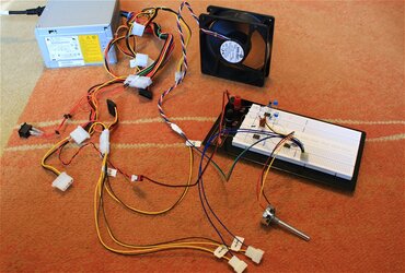
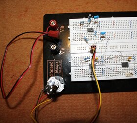
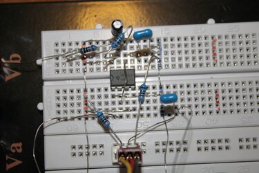
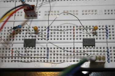
Sorry for the quality, i'm afraid you cannot detect the failure from it.
edit: Hahaha sorry, by watching the pics here i've found the failure. Now the circuit works perfectly
Last edited:
Busy ... as usual ! 
Thank you inVain my friend, that is so beautiful , can't wait to see it works.
Yep, Bob is right, actually if you read this thread from the beginning, BrutalForce did make the nidec version 1st, which much more simpler and it worked at ordinary pwm fan, but his beast sanyodenki fan is sucking too much power from the pwm signal source, so I did tweak it by adding a booster to amplify the signal. And through the process, I added other 0-100% version for completeness, so here we are now.
Congratulation Northor, another happy story !
I bet now you appreciate the breadboard even more than before right ?
Imagine you trouble shoot this problem at a soldered board, it will be a nightmare and usually this kind of small project, if it takes too long to troubleshoot, it will ended up abandoned and forgotten.
Now you've seen it your self that it works, trust me, this is the most important moment cause it gives you the confident to work on the soldered version, and even its not working for the 1st time, I believe you will be highly motivated to trouble shoot it.
Happy to hear this, and looking forward to see your work posted here, don't forget to share some short video on that controller on taming your beast fans collection there, must be real fun to watch.

running out of soldering tin, while got all the mood to gripping the soldering iron...
so I thought I'll just share the pics
and bing,
here's a tribute to you; a dip switch (hope I'm setting it right)
Thank you inVain my friend, that is so beautiful
 , can't wait to see it works.
See what i found at nidec america. Do they adept the need of publishing adequate pwm-support information from this thread?
That's where this thread came from I think
Yep, Bob is right, actually if you read this thread from the beginning, BrutalForce did make the nidec version 1st, which much more simpler and it worked at ordinary pwm fan, but his beast sanyodenki fan is sucking too much power from the pwm signal source, so I did tweak it by adding a booster to amplify the signal. And through the process, I added other 0-100% version for completeness, so here we are now.
So, i think having planned too much. My first try to built a 0%-100% circuit failed. The fan is running at around 50%, and the poti's adjustment takes no effect on that.
I've checked the circiut 3 times but cannot find any mistake.
I will try the 1%-99%-circuit next.
Sorry for the quality, i'm afraid you cannot detect the failure from it.
edit: Hahaha sorry, by watching the pics here i've found the failure. Now the circuit works perfectlyTime to redesign it and bring it on a soldered board as inVain does.
Congratulation Northor, another happy story !

I bet now you appreciate the breadboard even more than before right ?
Imagine you trouble shoot this problem at a soldered board, it will be a nightmare and usually this kind of small project, if it takes too long to troubleshoot, it will ended up abandoned and forgotten.
Now you've seen it your self that it works, trust me, this is the most important moment cause it gives you the confident to work on the soldered version, and even its not working for the 1st time, I believe you will be highly motivated to trouble shoot it.
Happy to hear this, and looking forward to see your work posted here, don't forget to share some short video on that controller on taming your beast fans collection there, must be real fun to watch.
- Joined
- Apr 4, 2011
edit: Hahaha sorry, by watching the pics here i've found the failure. Now the circuit works perfectlyTime to redesign it and bring it on a soldered board as inVain does.
great that you've manage to get the controller works...

I'm really sucks on bread boarding (maybe I'm bad at seeing such a straight line
 )
)and before you solder up everything, maybe I would be nice if you look for something to attach the PCB, so it will be very easy to mout the controller on your case
Thank you inVain my friend, that is so beautiful, can't wait to see it works.
pleasure is mine, bing
I totally forgot to buy myself the NPN transistors....
the only thing that I found on my drawer was a pair of C945 wich sadly didn't work on the kick start circuit

I hope that these transistors were doomed since I salvaged them from an old audio amp

we'll see what happened after I've replaced those two tansistors

Nice video MrDeltaFan ...err.. Northor  , thank you !
Should anyone trying to say that your double fan monster is too noisy and difficult to slow down, you should show them this video, this is the proof that monster fan like this can be deadly silent if needed. Cool toy and you sound quite happy there.
Compound fan like this is difficult to slow down if it is non pwm or you don't have a pwm controller because with ordinary linear fan controller, it will generate too much heat and has terrible efficiency.
Btw, is that pwm already soldered or still at breadboard stage ?
PS :
To embed a youtube video in the post, grab the suffix, the highlighted part from end of the youtube link -> http://www.youtube.com/watch?v=XRvU_wlTlGU
and edit your port and put into in your post exactly like this -> [yvid]XRvU_wlTlGU[/yvid]
- Joined
- Feb 22, 2009
- Thread Starter
- #887
Bing is right. Once I got the circuit right, it would run my Xigmatek Fan, but it fell short on the Beast. After the Inverted Schmitt buffer, it would run the Beast.
Again inVain, beautifull solder work.
Its amazing where this thread went to.
Again inVain, beautifull solder work.
Its amazing where this thread went to.
Thank you guys, without beeing motivated by yours and recieved your advice instantly, i've never had started the project. Until now the board is not soldered, but the parts are ordered. I have a plan 
Another question, my Delta TFC1212DE is inverted PWM, right?
Another question, my Delta TFC1212DE is inverted PWM, right?
- Joined
- Apr 4, 2011
thx Brutal 
nothor,
compared to intel stock fan and other commercial PWM PC fans, yes your TFC1212DE has the inverted PWM (at least on all TFC that I've handled before).
but since you build the 0-100% swapping the PWM signal is really easy. All you have to do is just swap the two outer pot legs connection and it's done....
and to take a peek on my project:

it's working, and it's fit the vga holder nicely (well it supposed to be inside :lol)....
except for the kick start section, since I don't have the transistors yet
nothor,
compared to intel stock fan and other commercial PWM PC fans, yes your TFC1212DE has the inverted PWM (at least on all TFC that I've handled before).
but since you build the 0-100% swapping the PWM signal is really easy. All you have to do is just swap the two outer pot legs connection and it's done....
and to take a peek on my project:

it's working, and it's fit the vga holder nicely (well it supposed to be inside :lol)....
except for the kick start section, since I don't have the transistors yet
Last edited:
Thank you guys, without beeing motivated by yours and recieved your advice instantly, i've never had started the project. Until now the board is not soldered, but the parts are ordered. I have a plan
Another question, my Delta TFC1212DE is inverted PWM, right?
My pleasure, its nice to see it works as you expected, just make sure you show us once you've finished your "plan", it sounds exciting thing is about to surface !
About the delta, I'm totally lost in decoding their part number, it looks like for those custom made like most used in server cooling, Delta probably put so many variations and combinations while not reflected by the model number.
 While for retail version, their part number is easy and complies to their public datasheet.
As inVain stated, its easier to try it yourself, especially you already have a working pwm controller, if its inverted, you will need to turn the pot in reverse than normal.
thx Brutal
and to take a peek on my project:
it's working, and it's fit the vga holder nicely (well it supposed to be inside :lol)....
except for the kick start section, since I don't have the transistors yet
That thing really looks like a pro made board
 and where did you buy those black pcb ? Did you paint it ? Its looks so cool & mean.
InVain, your controller board looks really fine and well built (i like the shrinking at the connectors) that it would not have been built better by LianLi either 
You're right, using a pwm-controller make it a pleasure to play with high cfm fans due to have a comfortable and full access to its whole performance and rpm spectrum. i do not know any non-pwm-fan which can run from 350 to 3.300 rpm (delta gfb1212vhg) or 560 up to 5.000 rpm (delta afc1212de 3.0A).
If you know any other must-have-been-played-with pwm-fans please let me know. Next is this one.
- Joined
- Apr 4, 2011
thx guys...
I really enjoying this project
you're right bing, I paint the PCB black. I want everthing look stealthy underneath that vga holder when I'm done.
to take a look back at this picture:

I'm really happy cause everything run smoothly according to plan, no more wasting the precious materials like before (at least until now
  )
)
and just in case, that somebody might missed that I use a 556 as the IST at the back of the circuit instead of a 555.
the schematic was derived from here: -> click
I've just adopt it to fit the 0-100% version,
and I'm using the 2nd dip switch to allow me to use the IST in "series" for driving multiple inverted and non-inverted fan in a single knob, or to configure the IST in "parallel" just in case that I might drive multiple monster fan in series, just like what Miah did
nothor,
your next wish list is so scary
I'd say go for it
and yeah....
the fun part of this controller is, it allow us to have the near "impossible" slow throttle stealth mode from a monster ear buster fan
again,
thx bing, and brutal
for starting this never ending PWM fever . you guys rocks
I really enjoying this project
you're right bing, I paint the PCB black. I want everthing look stealthy underneath that vga holder when I'm done.
to take a look back at this picture:

I'm really happy cause everything run smoothly according to plan, no more wasting the precious materials like before
 (at least until now
 and just in case, that somebody might missed that I use a 556 as the IST at the back of the circuit instead of a 555.
the schematic was derived from here: -> click
I've just adopt it to fit the 0-100% version,
and I'm using the 2nd dip switch to allow me to use the IST in "series" for driving multiple inverted and non-inverted fan in a single knob, or to configure the IST in "parallel" just in case that I might drive multiple monster fan in series, just like what Miah did
nothor,
your next wish list is so scary
I'd say go for it

and yeah....
the fun part of this controller is, it allow us to have the near "impossible" slow throttle stealth mode from a monster ear buster fan

again,
thx bing, and brutal
for starting this never ending PWM fever . you guys rocks

inVain, sound's great. Let us see the papst in an action-vid please.
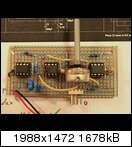
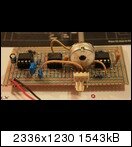
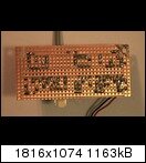
I've finished my first soldered version of that 0%-100% board. It sends a durable 0%-Signal, that means it doesnt work correctly :-( But i cant find the failure. The IC's work properly, i have testet them on the breadboard with success. But now i'm finished with ideas. Perhaps you will find the failure by check the circuit on that picture.


I've finished my first soldered version of that 0%-100% board. It sends a durable 0%-Signal, that means it doesnt work correctly :-( But i cant find the failure. The IC's work properly, i have testet them on the breadboard with success. But now i'm finished with ideas. Perhaps you will find the failure by check the circuit on that picture.
- Joined
- Apr 4, 2011
Thx nothor 
sorry to hear the problem you had on the soldered version.
I suggest you to recheck the connection on IC2 (LM311)...
and I've highlighted the potential error on your connection (but I might be wrong to :/)
it's marked by the purple circle with the black number:

If I'm not mistaken, you've connected the Inverted Scmitt Trigger to pin #8 on IC2 in this case you should connect it to pin #7.
Please update us with your progress
sorry to hear the problem you had on the soldered version.
I suggest you to recheck the connection on IC2 (LM311)...
and I've highlighted the potential error on your connection (but I might be wrong to :/)
it's marked by the purple circle with the black number:

If I'm not mistaken, you've connected the Inverted Scmitt Trigger to pin #8 on IC2 in this case you should connect it to pin #7.
Please update us with your progress
Thank you very much, inVain, due to your advice i've rechecked the board and for sure, i've found a connection which was not soldered correctly. But now the board brings out an 100% pwm-signal instead of that 0% before. Connected fans run at full speed instead of full stop. And still, i cannot regulate it with the poti. I removed the poti to check it, but it works correctly. The failure must be with in the circuit. I've painted the connection it the following picture, because some details cannot be seen. That had set yu on the wrong track., im sorry for that.

EDIT:
a better picture i think:

EDIT:
a better picture i think:
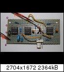
Last edited:
- Joined
- Apr 4, 2011
ah sorry for the wrong reading 
and thx for adding the signal path nothor (it surely help others to read your circuit, and diagnose error )
)
and after 2nd reading, everything looks okay to me.....
recently, I've had the same problem as yours. my PWM controller's having a strange behaviour after I turned off the PC last morning.
sometimes the fan spin at 100%, sometimes it stop, the pot doesn't respond at all. I've check my connection for many times, swaping the components with the new ones, and still the problem occur.
so, I reheated my every single solder joints (this is my desperate resort actually), and strangely, now the PWM controller works okay.
while I'm writing this post, my controller is running about 30 minutes without problem.
hope my experience will help you somehow.
and I suggest you try to swap the LM311, it's really easy to broke somehow :/
cheers
edit:
and now my PWM is running 100% again
I'll try to fix this somehow, and let's give up another day
and thx for adding the signal path nothor (it surely help others to read your circuit, and diagnose error
 )
)and after 2nd reading, everything looks okay to me.....
recently, I've had the same problem as yours. my PWM controller's having a strange behaviour after I turned off the PC last morning.
sometimes the fan spin at 100%, sometimes it stop, the pot doesn't respond at all. I've check my connection for many times, swaping the components with the new ones, and still the problem occur.
so, I reheated my every single solder joints (this is my desperate resort actually), and strangely, now the PWM controller works okay.
while I'm writing this post, my controller is running about 30 minutes without problem.
hope my experience will help you somehow.
and I suggest you try to swap the LM311, it's really easy to broke somehow :/
cheers
edit:
and now my PWM is running 100% again

I'll try to fix this somehow, and let's give up another day
Last edited:
Heureka!!!! 

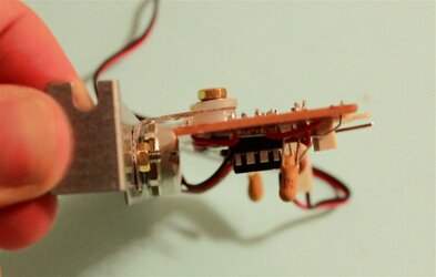
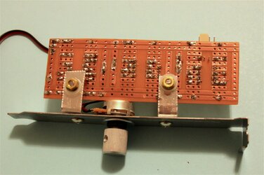
Fortunately i've ordered enough parts to build up three controllers (one left on breadboard), thats what i've done today. I took another board that looks similar to the plan bing had postet in #25, so it was quite easy to design. The result now looks a bit DIY but i love it It's the perfect mate to pwm-fans.
Thanks to you all!

What i am wondering is the behaviour of the poti. Connectet do the breadboard-controller, it brings no full stop to Delta GFB1212VHG, but now beeing part to the soldered one, it brings it to full stop? Before had finished the soldered version i thought it is caused by the poti itself, but now i'm not sure any more...
For you finally my first soldered pwm-controller in pictures.
Next is the 2 % - 98% version.
inVain, i'm sorry to hear abou the strange behavior of your controller. Please tell us if you find the bug inside.


Fortunately i've ordered enough parts to build up three controllers (one left on breadboard), thats what i've done today. I took another board that looks similar to the plan bing had postet in #25, so it was quite easy to design. The result now looks a bit DIY but i love it
Thanks to you all!


What i am wondering is the behaviour of the poti. Connectet do the breadboard-controller, it brings no full stop to Delta GFB1212VHG, but now beeing part to the soldered one, it brings it to full stop? Before had finished the soldered version i thought it is caused by the poti itself, but now i'm not sure any more...
For you finally my first soldered pwm-controller in pictures.
Next is the 2 % - 98% version.
inVain, i'm sorry to hear abou the strange behavior of your controller. Please tell us if you find the bug inside.
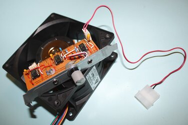
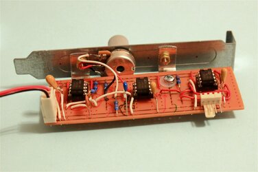
- Joined
- Apr 4, 2011
LOL, now I've found my problem...
I got a bad connection between R2-C1-pin#2-pin#6 on IC 1, right after I've disassembled my PWM controller and tried to draw the schematic in a software
I guess too much dealing with the 556 has made my eyes blurry to see the pin connections on the 555
well at least, I've found some hints for my future build:
for C4, better type with value of 100pF will give you smoother control with your pot
for R3 and R4, the nearer of their actual value with the pot's value, will made the controlling behaviour better
nothor, congratz
it's really good to have a working controller isn't it....
and I guess you're ready to slam that board into your case
and now, I'm ready to watch some more loud rigs of yours
and for your poti response, I suggest you to measure your R3, R4, and your pot value with the DMM (see above for explanations)
cheers
I got a bad connection between R2-C1-pin#2-pin#6 on IC 1, right after I've disassembled my PWM controller and tried to draw the schematic in a software
I guess too much dealing with the 556 has made my eyes blurry to see the pin connections on the 555

well at least, I've found some hints for my future build:
for C4, better type with value of 100pF will give you smoother control with your pot
for R3 and R4, the nearer of their actual value with the pot's value, will made the controlling behaviour better
nothor, congratz

it's really good to have a working controller isn't it....
and I guess you're ready to slam that board into your case

and now, I'm ready to watch some more loud rigs of yours

and for your poti response, I suggest you to measure your R3, R4, and your pot value with the DMM (see above for explanations)
cheers
Similar threads
- Replies
- 4
- Views
- 2K
- Replies
- 6
- Views
- 1K
- Replies
- 32
- Views
- 20K

